Wiring harness design in CATIA V5 - 3D modeling Week 5 & 6 Challenge
Introduction:-
- The wiring harness routing consists of an assembly of the geometrical bundle and electrical bundle. For mechanical wiring harnesses, the assembly of a geometrical bundle is the main component.
- For assembly of geometrical bundle, the connector, clips, grommets, must be electrically defined before entering into the wiring harness assembly.
Assign electrical properties to connectors:-
- The required connector is downloaded from te.com. The electrical properties are given to all the connectors using electrical part design.
- Firstly, go to electrical part design.
- Define the connectors by using the connector command.
- Define the connector's connection point and bundle connection point to the connectors.
Creating wiring harness:-
- Create the assembly of geometrical bundle product in CATIA V5.
- Open all the required connectors into the geometrical bundle assembly product. note that all the connectors must be electrically defined.
- As mentioned in the figure, connectors are placed at the required positions using the SNAP, SMART MOVE, COORDINATE SYSTEM, and MANIPULATION COMMANDS.
- Now enter into the wiring harness assembly workbench.
- Click on MULTI-BRANCHABLE DOCUMENT, give the branch diameter and the bend ratio. open the route definition and connect the bundle connection points.
- To give the routing from the main branch use ADD BRANCH POINT at the required location and give the sub-branches.
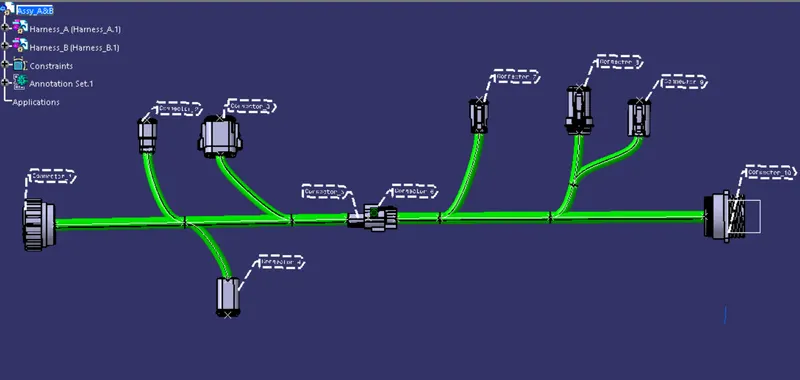
Final harness assembly with annotation:-
Check Bundle connectivity:-
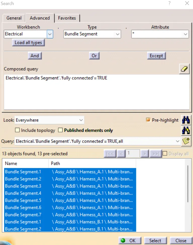
- Once the bundle is built, now check all bundle wire connection is fully connected or not.
- Steps: Edit-Search-Advanced
Create electrical part file into the mechanical part file:-
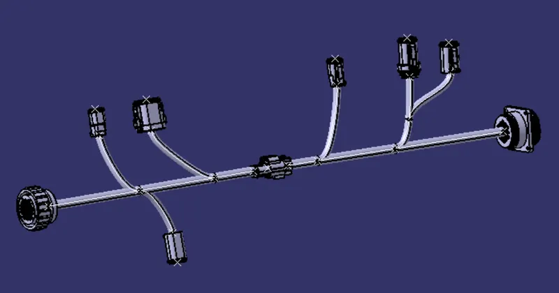
- Select assembly geometrical bundle, go to tools-generate CATPart from product option, The CATPart is generated. Now convert CATPart into igs file which is most commonly used to file for 3D model.
Conclusion:-
- I understand, how to define electrical part to the connector then bundle entry and connector connection point, after making two different harnesses then assembled them and gave annotations to a connector. Conversion of product file into igs file.