Photo Realistic Rendering
Aim & objective:
- To learn solidWorks software interface and simultaneously sketch or model the parts of American chopper.
- Apply appearance, scene, decals &material.
- Also apply the camera view, rendering to the vehicle, changing the background of vehicle with adjusting the shadow and daylight scene to the vehicle.
- Assembles the parts which we draw in part design.
- Do visualization of the assembled chopper design.
Introduction:
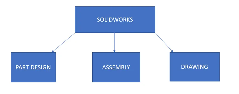
SolidWorks is a mechanical design software were we design 2D and 3D CAD (Computer Aided Drafting) models. It helps to design product better, faster and more efficient.
Common tools which used in modelling of chopper:
- Plane:-Here the selection of the plane first on which we design the part.
- Sketch:-sketch 2D &3D model drawn on the plane.
- Smart Dimension:-By using the smart dimension we apply the correct dimension to the part for obtaining desired shape to the model.
- Chamfer:-It gives the sloping edge to the corner of the part.
- Fillet:-It provides round edge at the corner.
- Trim Entities:-Cut the unwanted line in the part, also the excess line and circle.
- Convert Entities:-By using given tool easy to sketched into the other plane or same plane with same dimension value.
- Offset:-It adds the offset line parallel to the line also same for the circle.
- Mirror Entities:-Mirror the drawn design same to the another side of the plane or construction line.
- Pattern:-There are the different types of the pattern ,where the same object can be draw continue in line also in curve portion w.r.t to centre line or circular portion w.r.t centre.
- Extrude Boss/Base:-By using solid body in or two direction.
- Revolve Boss/Base:-Used to revolve the sketch with the reference of axis or lines in a solid form.
- Swept Boss/Base:- It provides a solid body by closed profile along an open and closed path.
- Extrude path:-By using given tool ,remove the material from solid body.
- Shell:-The shell tool hollows out a part.
- Appearance:-Apply different materials and different look to the part.
- Decals:-By using given tools painted stickers to be applied.
Views:
- Zoom to fit
- Zoom to area
- Rotate view
- Roll view
- Pan
- View orientation
- Hide item
- Edit scene
Components of American Chopper:
- Transmission belt
- Padel
- Kickstand
- Front fender
- Rear fender
- Front wheel
- Rear wheel
- Chain
- Oil tank
- Gas tank
- Engine
- Front fork
- Chassis
Design Methodology:
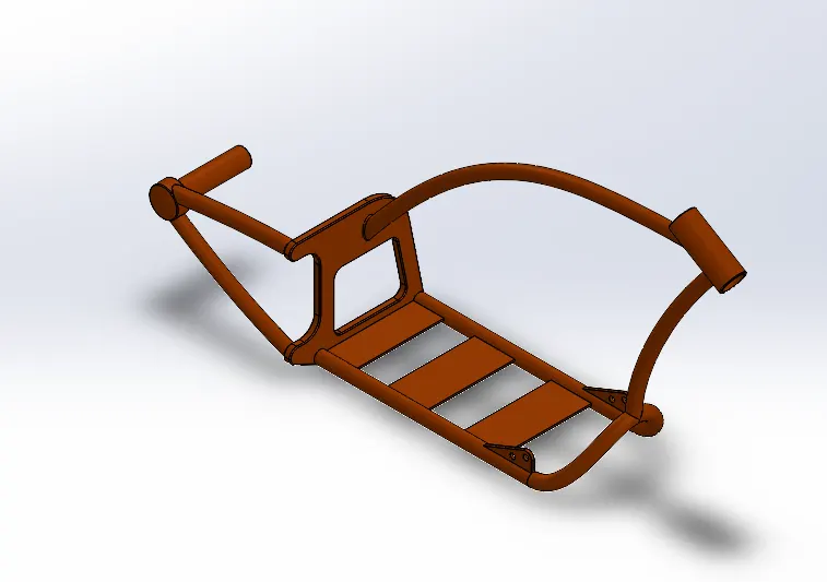
Chassis:
Chassis is the bone of the vehicle. it is a structural unit which bear all the load of the vehicle body. The purpose of the chassis is provides proper support and balance of the vehicle. All components connected to the chassis directly and indirectly. Another purpose of the chassis is to provide safety to the parts which mounted over the chassis.
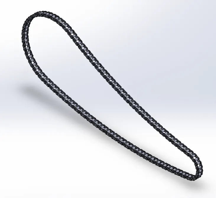
Chain:
Chain is mounted over the sprocket. which is used to transfer mechanical power from one sprocket to another sprocket.
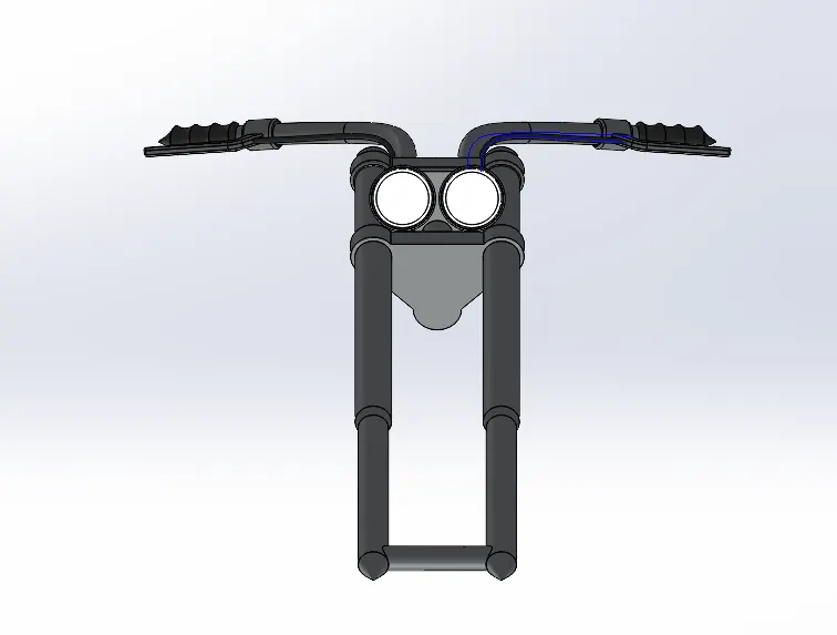
Front Fork:
It holds the front wheel. It is made up of different types of material like steel, titanium, and carbon fibre. It gives direction to the vehicle while riding.
Fenders:
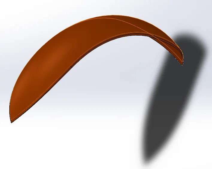
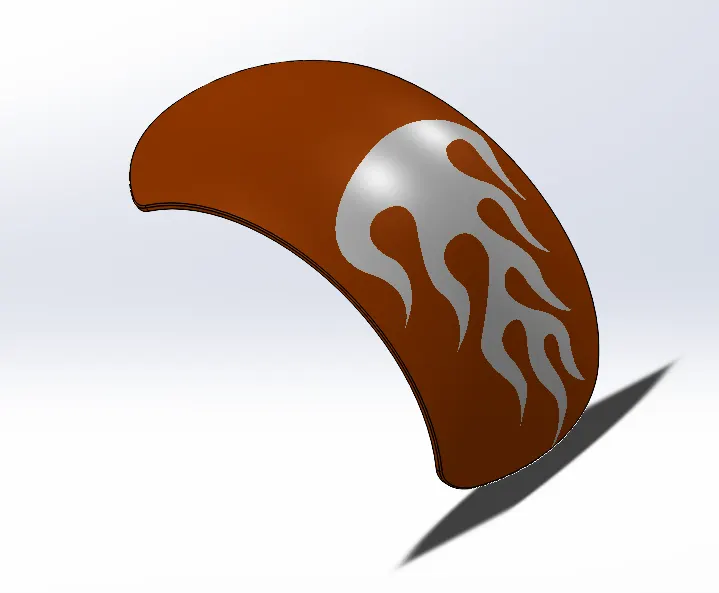
Fender Is installed over the wheel. It prevents water and mud spray.
Wheel:
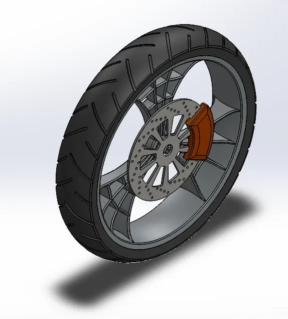
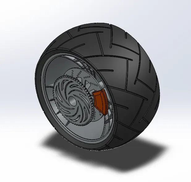
It is made up of rubber material which is flexible in nature. It is mounted over the rim. wheel provides proper gripping to the wheel surface for traction and serve cushion for vehicle while riding.
Stand:
It is made up of hard material located in the lower portion of the chassis. also gives standby mode to the vehicle. total load of the vehicle is on stand.
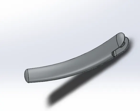
Engine:
It is the heart of vehicle. V-Engine is used in chopper.it generates mechanical power and gives motion to the vehicle.
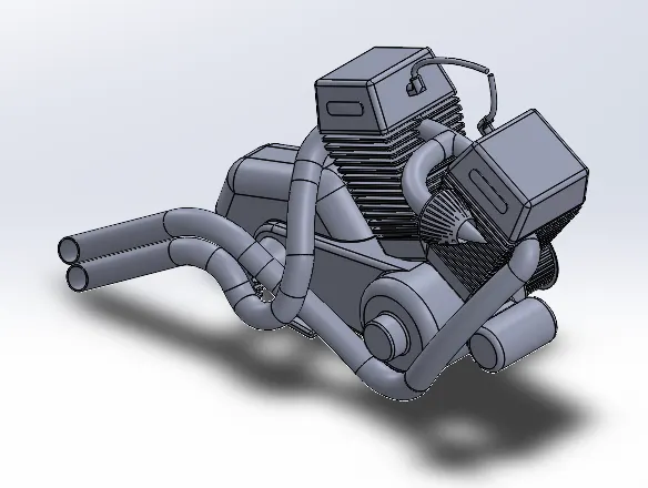
Oil tank:
It is acts as a reservoir. Flammable fuel is inside the oil tank.
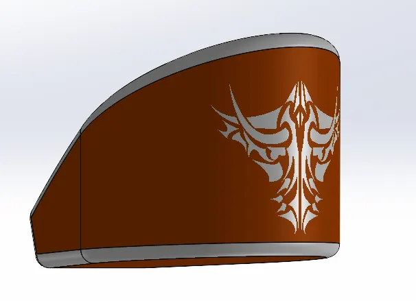
Gas tank:
It is acts as reservoir.
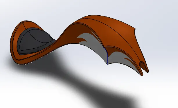
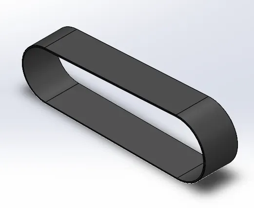
Transmission belt:
It is made of flexible material which transmites power from one shaft to another.
Assembly of part:
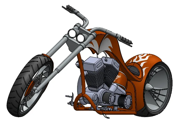
After drawn each parts of the vehicle, then assemble all the part. Here insert component all parts which we drawn then browse one by one parts, first of all fix the one component on the work base. Giving relation to the fix part with assembly for proper adjustment to the design. While assemble the parts matting of plane to plane also giving standard mate/advance mate/mechanical mate. Insides the assembly -sign indicate part is over defined and +sign indicates under defined. While assembling oversized or irregular shape can be redefined on the spot.
Rendering:
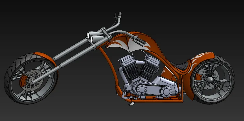
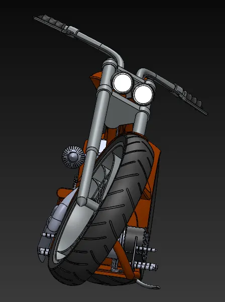
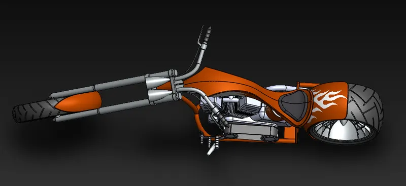
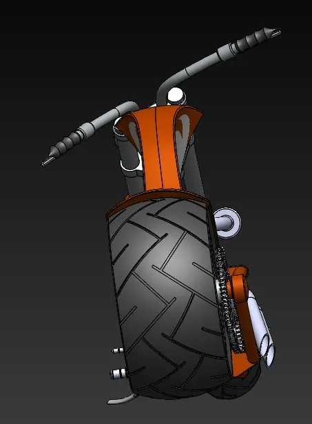
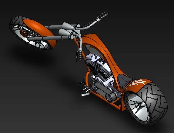
Here, the product to be seen under environmental condition with different views also applying camera view to the vehicle.
Conclusion:
To understand how to develop the American chopper by using different tools in solidworks.