Week 8 - Challenge 1 - Draft Analysis on a Fan Cover
DRAFT ANALYSIS ON A FAN COVER
Objective:-The main objective is to perform draft analysis to check if the part has the given draft on its all faces, and to determine the tooling axis.
Draft:-It is tool used in CATIA to make the face taper with respect to tooling axis. Tooling axis is the direction of mould part ejection.
Why draft is necessary:-
A functional part for injection moulding has to have drafts facing both cavity and core sides to reduce the risk of damage to the parts and ensure ejection. As the molten plastic flow into the closed die and fills the cavity ,the material shrinks inside the mould upon cooling and as a result grips the core. Without any taper , the part would come out scratched while increasing wear and tear on the mould and shortening the tool life.
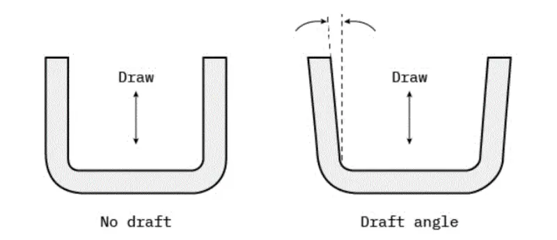
Draft Angle Recommendation:-
- 3-degree is nominal draft.
- 0.5-is minimum draft which increase cost of manufacturing.
- 7-degree degree for textured faces.
Steps involve in draft analysis :-
Step 1:-Merging of class A surface be connected no gap should be there we can check it using join command or boundary command if there is gap then green colour line appear.
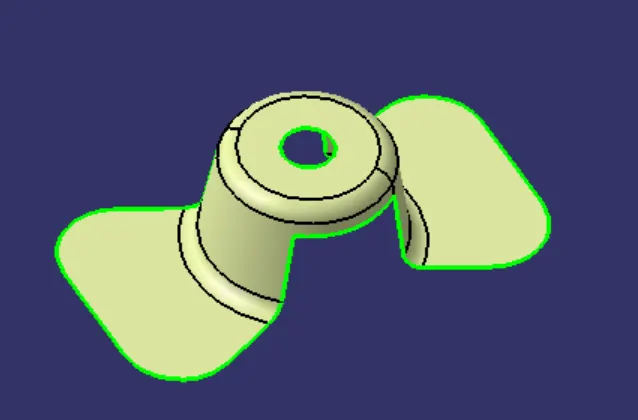
Step 2:- Now we analyse the best tooling direction using X/Y/Z plane we create dummy tooling line for reference.
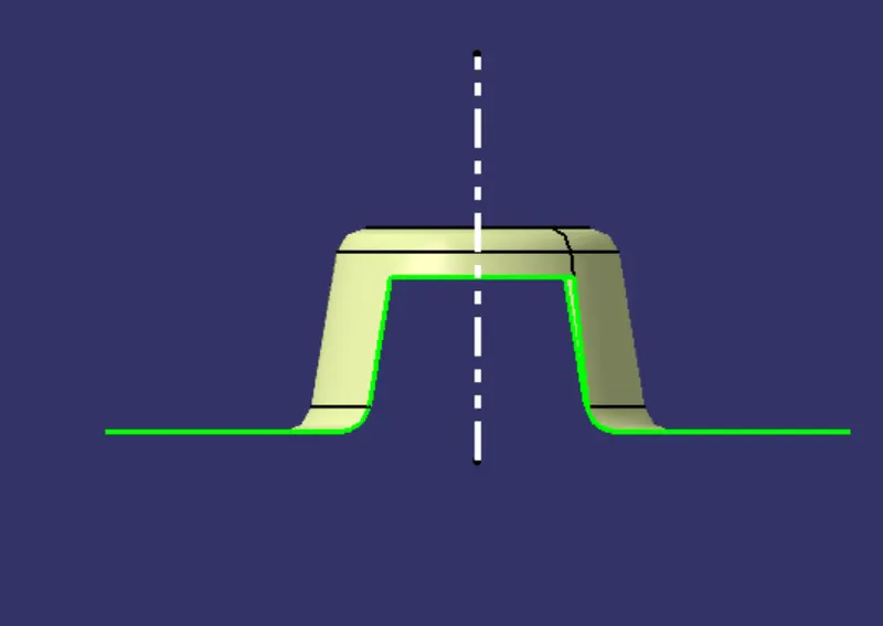
Step 3:- Now we create tooling clearance along X/Y direction using the intersection of plane with class A surface.
We intersect class A surface with XY/YZ/ZX plane and create the reference line on the surface which might face problem during tool ejection.
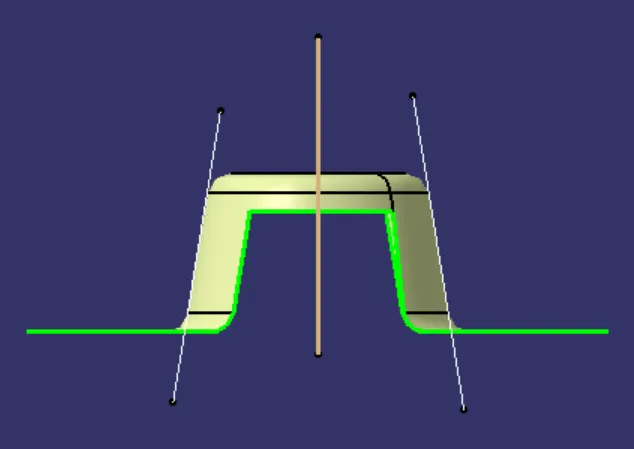
Tooling direction along X-axis .
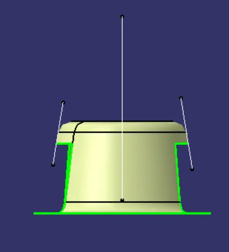
Bisecting line concept:-With the help of reference lines we make bisecting line which is on the same plane as the reference lines but are in normal direction. They are the either vertical or horizontal lines at the point of intersection of reference lines.
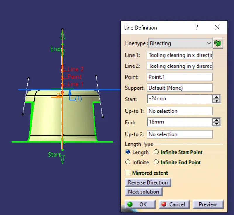
Step 4:-Making the tooling direction line :-When We get the tooling direction in both X and Y direction then we use bisecting line to generate the tooling axis.
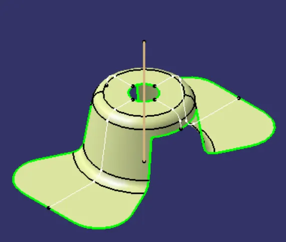
Step 5:-Publish the tooling line class A surface we publish the output so that it can be used further for making thick body class B surface.
Step 6:-
Draft analysis:-
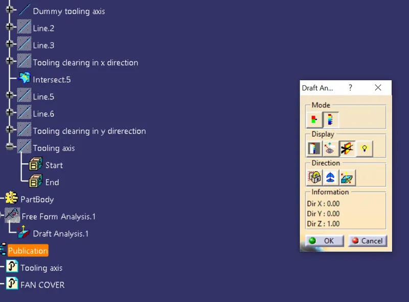
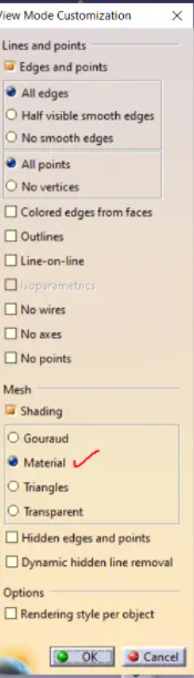
1.We first change view parameters into customised mode with material check.
2.Click the insert tool bar then draft analysis icon.
Now draft analysis tool will appear on screen, it gives information about colour ,display and direction.
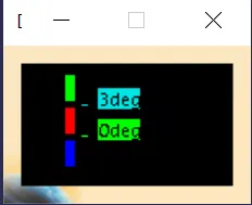
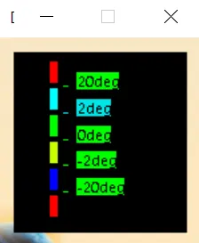
Mode :-This option gives details about colour coding and with the help of this we can set parameters of draft analysis also if we want to change draft angle value.
Display option:-
1.Is the first option used for hide and show the colour.
2.second option is used for analysis under point it gives the value of draft with respect to tooling axis selected at given point of the surfce.
circle indicating plane tangent to surface.
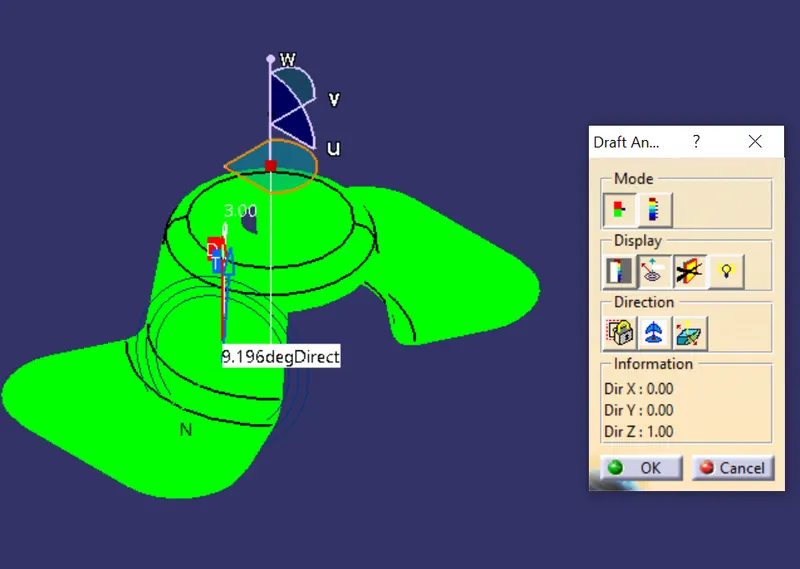
Direction:-In this we set the compass on the tooling direction once the compass set on tooling axis we lock it so that it does not change also we can flip the direction of the tooling if the compass direction is not as per our tooling direction.
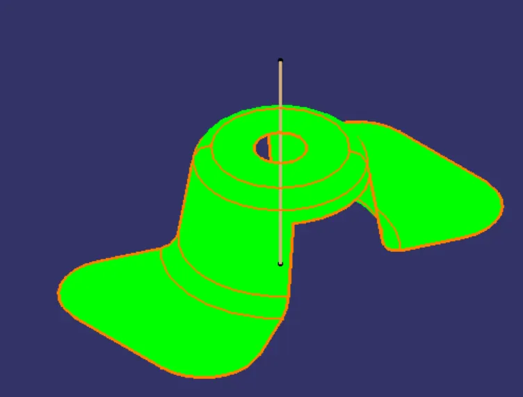
Final draft analysis and isometric view :-As the all surfaces are in green colour this indicates the surface have draft more than 2 degree along the tooling direction indicating that our part can be easily ejected in tooing direction.
Front view:-
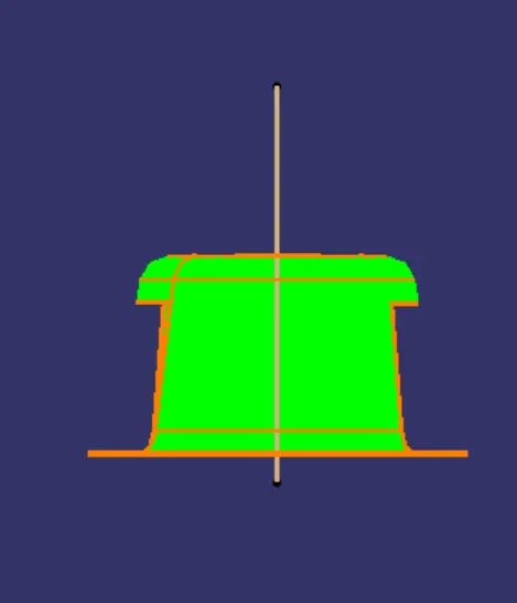
Side view:-
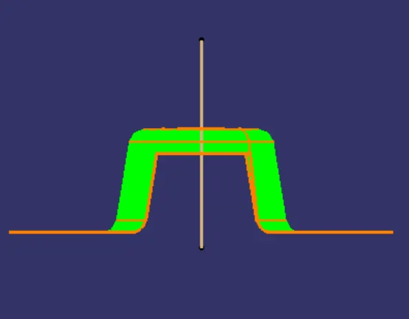
Top view:-