Wiring harness design in CATIA V5 - 3D modeling Week 5 & 6 Challenge
To create the wiring harness assemblies according to the given layouts and make an inter-connection between them.
Process :
First all the given connectors are downloaded, electrically defined and stored into the specific catalogues.
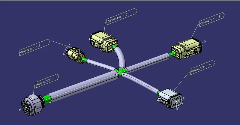
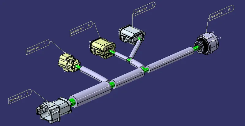
Then the connectors are placed in the geometrical bundel according to the two layouts.
After that the bundells are routed to all the electrically defined connectros in eacch geometrical bundel assemblies
The routing is made with appropriate tangency for each connectors and at each branch points.
The protective covering is added for all the bundel segments keeping the end extremities at 15mm.
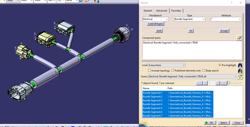
Then the two bundels are gone through the search command for the connection check.
After the connection check the two geometrical assemblies are added into a single context assembly.
here the electrical connection is made between (5) & (6) connectors.
after the connection the Product file of context assembly is converted into the CATPart.
Then the CATPart is saved into the iges part file so that can be used in different CAD Tools.
The below are the given layouts.
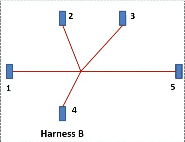
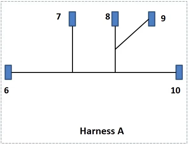
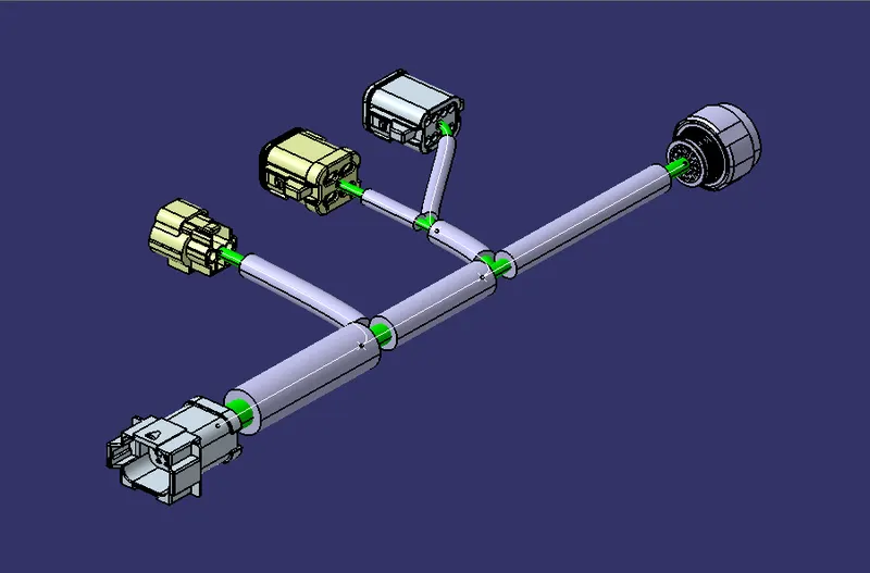
Harness - A
Harness - B
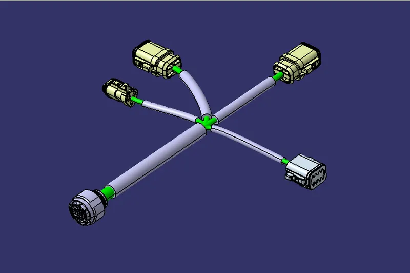
Bundel Connection Check
Harness - B
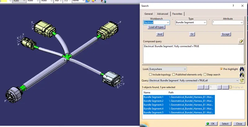
Harness - A
Annotation of Harness - B
Annotation of Harness - A
Harness - A&B in a single Context Assembly
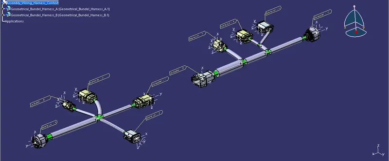
Making connection between two harness assemblies
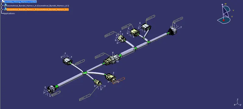
Generation of CAT.part of harness assembly from Product file
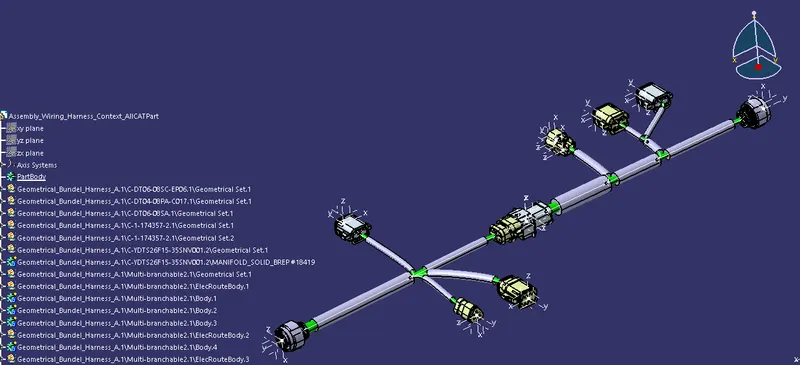
Hence the Harness assemblies are made using CATIA Electrical harness workbench according to the given layouts.