Wiring harness design in CATIA V5 - 3D modeling Week 5 & 6 Challenge
Aim: - To Define the mechanical components electrically and prepare the catalog for harness 1 and harness 2 and prepare the interconnection for harnesses A and B.
OBJECTIVE
To design WIRING_HARNESS_ROUTING by using given PART_WORKBENCH, ELECTRICAL_PART_WORKBENCH, ELECTRICAL_HARNESS_ASSEMBLY & INSTALLATION, ELECTRICAL_ASSEMBLY_WORKBENCH.
Software
CATIA v5
INPUTS
CONNECTORS AND design Layout
Layout
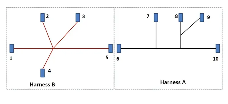
Connectors
|
INPUT_CONNECTORS |
|||
|
S.NO |
HARNESS_A |
S.NO |
HARNESS_B |
|
6. |
C-DT04-08PA-C017 |
1 |
C-YDTS26F15-35SNV001 |
|
7. |
C-1-174357-2 |
2 |
C-DT06-3S-CP01 |
|
8. |
C-DT06-08SA-CE01 |
3 |
C-DT06-08SA-CE04 |
|
9. |
C-DT06-08SA-EP07 |
4 |
C-DT06-08SA-EP07 |
|
10 |
C-YDTS26F15-35SNV001 |
5 |
C-DT06-08SA-CE13 |
HARNESS_A
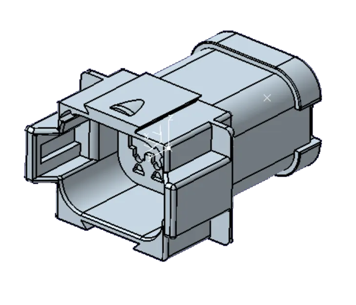
C-DT04-08PA-C017
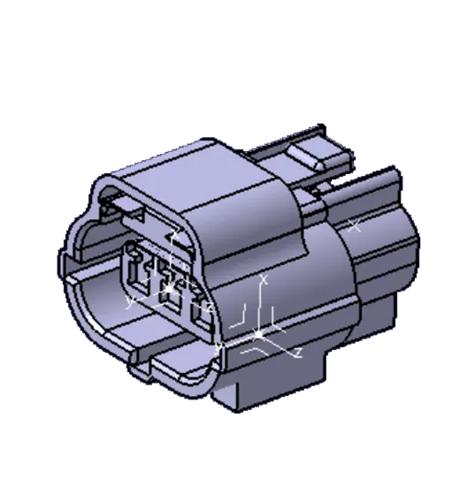
C-1-174357-2
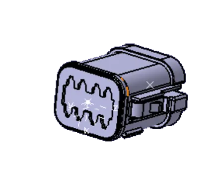
C-DT06-08SA-CE01
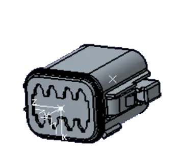
C-DT06-08SA-EP07
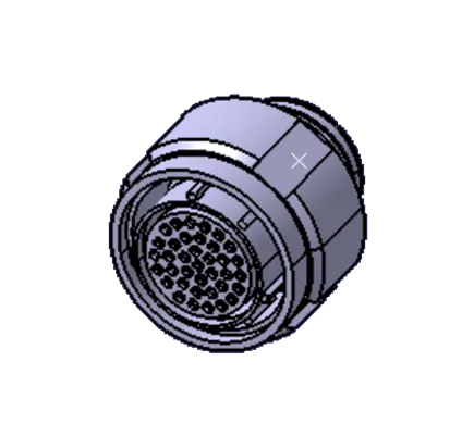
C-YDTS26F15-35SNV00
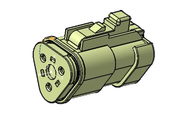
C-DT06-3S-CP01
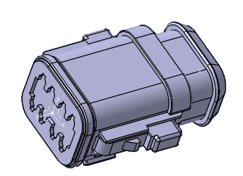
C-DT06-08SA-CE04
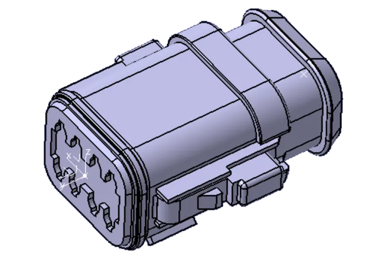
C-DT06-08SA-CE13
Procedure
Download the connector files and convert the file into CATpart files and save. Then create a new catalog for the HARNESS_A&B and save it in the Catalog group.
Now open the connector CADpart file in the Part workbench and add point and Axis for the connector to define the component.
To define the Connector as Electrically Define Open the Electrical Design Workbench and select DEFINE CONNECTOR and select the component and enter the number of terminals and select OK .
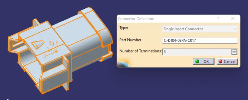
Fig Define as Connector
Now select the BUNDLE connection command and select the connector and select the bundle entry face and the midpoint for bundle entry and face for representation select OK.
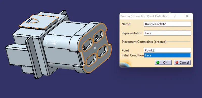
Fig Bundle Entry Point
Now open the CONNECTOR connection Point definition command and select the connector and define the connector connection point and Contact as Point Coincidence as Y-axis and Orientation as X-axis. Select OK.
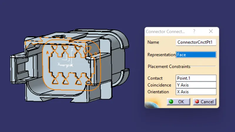
Fig Connector Connection Definition
And save the file and ADDED to catalog repeat the same process for all the connectors for Harness_A&B.
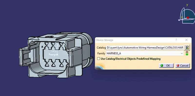
Fig catalog for HARNESS_A
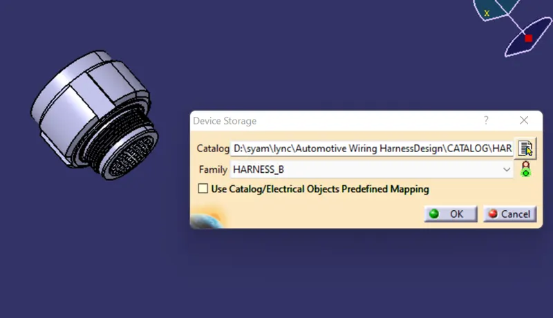
Fig catalog for HARNESS_A
STEP-2
Open the ASSEMBLY WORKBENCH and import the Harness-A components and place them as shown in the layout by using the COMPASS in the workbench. then open the file in the ELECTRIC HARNESS ASSEMBLY and convert the product file to the Electric define by using the GEOMETRICAL BUNDLE command and selecting the product file
For creating the bundle select the MULTI-BRANCHABLE DOCUMENT COMMAND and select the connectors shown in the above layout.
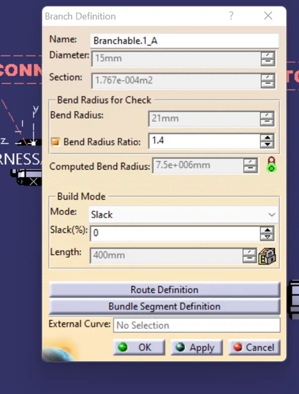
Fig multi-Blanchable
Repeat the same process for the Harness-B and save the file
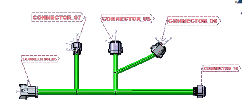
Fig Harness-A Multi-Branchable
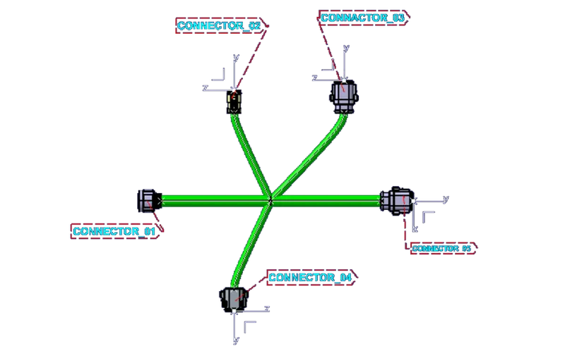
Fig Harness-B Multi-Brachable
Then create a new Product file and name as HARNESS_A&B import the Harness_A and Harness_B file in the assembly and make a connection for the connector _5and Connector_6 in the assembly file. And add give the annotations for all the connectors and check the connectivity for the assembly.
For connecting checking go to EDIT—SEARCH—ADVANCE—in WORKBENCH select -ELECTRICAL in type select BUNDLE SEGMENT—in attribute select FULLY DEFINED one popup window opens select TRUE and select SEARCH option it shows the what are connections are connected and what is not connected.
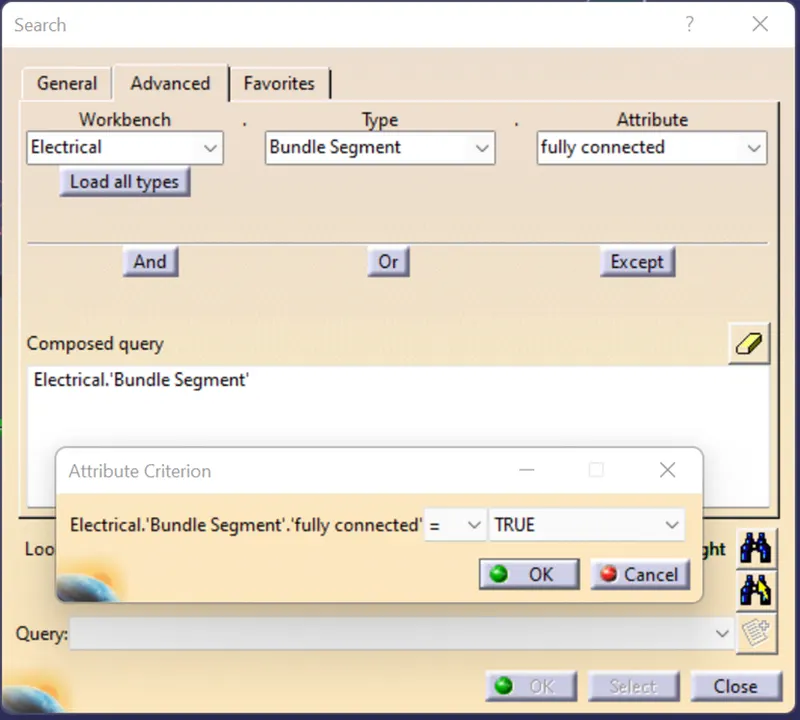
Fig search interface
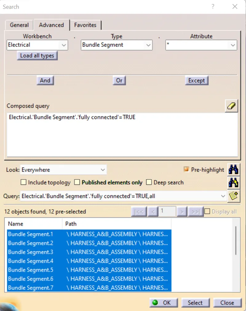
Fig search result
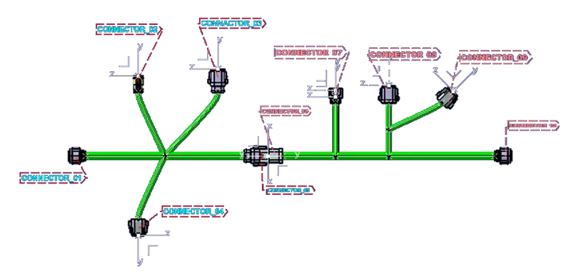
Fig final assembly for Harness-A and Harness_B
For the 2D detailing save the file to CATpart file for that select the TOOLS option and select the GENERATE_CADpart from PRODUCT and enter the name of the file and save it as a CADpart file.
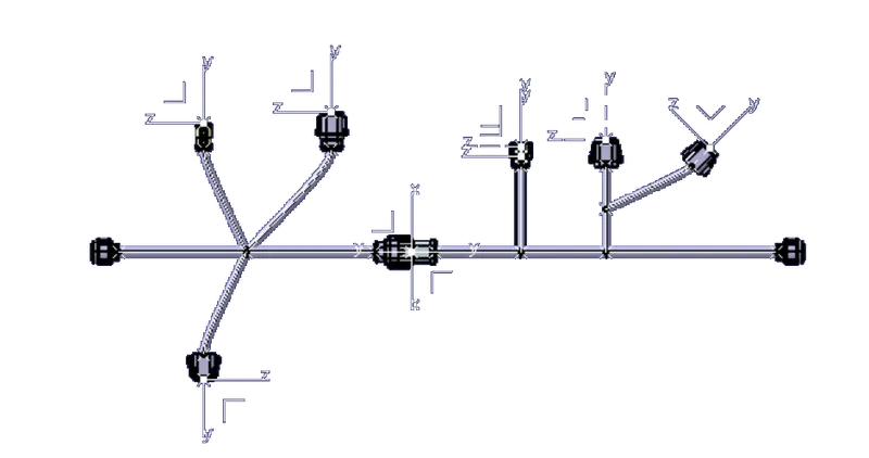
Fig CADpart_file
Result:- From the given inputs created Harness_A and Harness_B and added Connection in between Harness_A&B and converted into CADpart file for that connections.