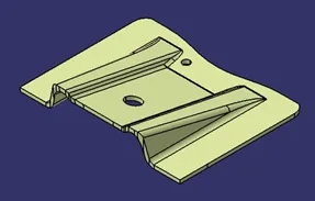
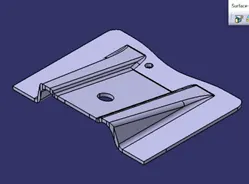
Week 8 - Challenge 2 - Base Bracket Design
Procedure To Create Class-B & Class-C & Draft Analysis of Base Bracket
Step -1: - check the Class-A surface for all joints are connected properly if any surfaces are required to join use the join tool in Join- Healing toolbar or use the Boundary command in the Extract toolbar
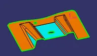
Step -2: - check component in all 3 Axis the component. In which direction component can clear all the features in the tooling axis. In my case, I assumed Z-Axis is the tooling direction. And check the line Bisection method
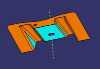
Step -3: - Take hole or the large Flat surface is the tooling axis point in my case I took hole as my base of creation of tooling axis and created a Dummy Tooling Axis with respect to Z-Axis to create dummy tooling Axis take a point at the center of the hole and draw a line with Point and Direction option select the point and in direction select the Z-of the component and extend the line to the required length and Name a Dummy Axis
Step -4: -Need to check the component with the other two Axis (X, Y). For that, we need to create intersect of the component that we need to check. in my case X direction can clear the tooling direction easily b/c there is know Complicate features in that axis. Now coming to Y-Axis take the point as center and create YZ-plane at the point and use Intersection Command select the Class-A Surface as the First Element and select the create plane as the second element. The intersection of the Y-axis has been created. Use line command and use Point-Point option inline command draw the line for the component that had to clear the Tooling Axis on both the side and use Bisecting option in Line Command select the two lines the Tooling Axis of the component is created and name the line as tooling axis.
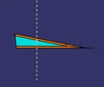
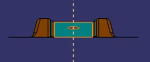
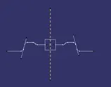
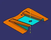
Step -5: -Next step is to do a Draft Analysis for the component for that need to change the material properties of the component then go to insert Analysis Feature Draft Analysis. Draft analysis interface will open and use compose option and select the Ucs and fix the axis to the component. And check the draft position correct or not if it is in the wrong direction change to inverse the draft direction. And hide the draft analysis.
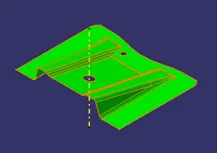
Step -6: - Insert a geometric set and name it a Base Bracket. And insert another geometric set and name as B- surface (it is the surface that gives the thickness from the Class-A surface , and also all the Engineering attachments are added to B-Surface )for that need to offset Class-A surface with the required thickness for this component 2.5mm is the thickness. When we are doing Offset fillets creates some issues in the Class -C surface so leave the fillets and offset the other parts. In the component, there are mainly 2-ribs and connecting face and main base are there start with the Ribs
Step -7: - insert the geometric set and name as Rib-1 and Extract the faces of the rib and use Untrim for the Surface and Extrapolate the surfaces of 10mm for the other three surfaces and use trim the surface to the required surface and Offset the surface with 2.5mm downward Direction and change the different color to offset surface.
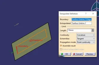
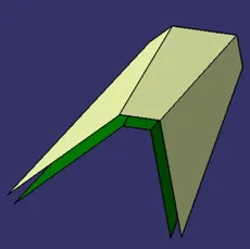
Step -8: - Repeat the same steps for the others side of the Ribs for that insert another Geometric set and name as Rib-2 and insert all the Rib-2 features in rib -2 and check the two ribs with Class-A surface. If any changes are required correct from there itself.
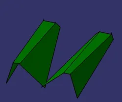
Step -9: - to create the middle flat surface add a Geometrical set and name it as Base Surface in B-surface and Extract the surface and Untrim the surface and Offset of 2.5mm below the surface and Extrapolate it with 10mm. And also repeat the same procedure for the main base surface
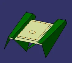
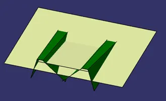
Step -10: -Insert a geometric set with base bracket and name as Final Trims and trim the base surfaces with the Ribs and add the fillets to the B-surface check the Radius of the A-surface and add the thickness for the Radius give the fillets for the surface and change the required color to the final surface. This the B-surface completed and next create C-surface.
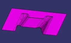
Step -11: -insert a new geometric set and name as C-Surface (the surface which connects the A-surface and B-surface is a C-surface).create Boundary for A-surface and use SWEEP tool to create the surface open sweep tool and use line option in it select the boundary surface and select the tooling axis as the second reference and give an angle of 30 and extend up to the surface that covers the B-surface and repeat the same operation for the holes and join the Class-A surface and C- Surface with the joining tool.
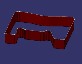
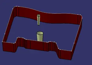
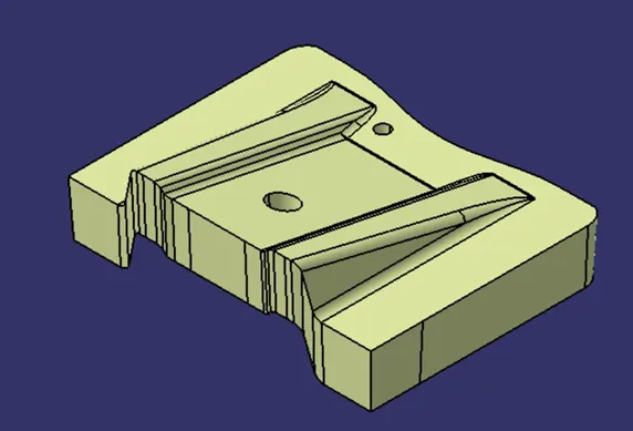
Step -12: - insert another geometry set and name as Trim Surface in the set trim the joined class-A and Class-C with Class -B and check the final surface is fully joined if not rectify the surface. And move to the PART DESIGN Workbench use Close-Surface command in Surface Base features toolBar. And select the Final Trim Surface And Enter final part was formed