Week 9 Challenge
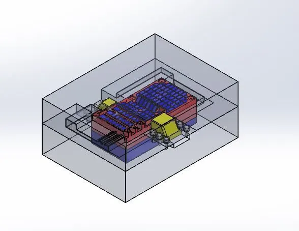
Slider & Insert
- Step-11 and then create the extra attachments of the slider and to attach the slider screw sketch on the slider side part and with the 40mm length and in vertical ¾ of the slider height with 300 of the angle use extrude cut option to remove the parts
- Step-12 and clear the way of the slider and add extra material for screws and guideways of the slider for guideways 5mm and screws 15mm. and insert the component in a new folder and add a new folder and import the slider component into the folder name the folder as SLIDER01
- Step-13 To create the second slider start sketch on the author plane which covers the slider part and make the dimensions of the sketch and create the plane with 0 references make slipt common in the Direct-Editing toolbar select the sketch and plane as the main source and make the cut in the command and select the object to be split
- Step-14 made extra attachments of the slider by extruding to the surface the component to be extended
- Step-15 for the component core also had an extension of the slider using the same plane and split the slider and combine the 2 slider splits into a slider and make the wadge on the slider with 40mm distance from the point and with an angle of 300and remove the extra part of the slider by using extrude cut option. And add extra guides and with 5mm with extruding till the wedge and make guideways for the slider and free to travel area free in the way and insert the slider into a new part file and name as slider02
- Step-16 Add the new part file into the assembly and insert
- Step-17 for the core block depth of the slots is high it makes manufacturing difficult so we need create an insert block for the core block for that edit core block and extend the thickness of the core block up to 30mm by moving to face command indirect editing and select the plane of the component and create an extra plane with 20mm below the selected plane
- Step-18 Select the top surface create a sketch and use spit command indirect editing command toolbar follow the same process for the second insert block and get the blue color for the blocks it is easy for the machining process
- Step-19 For creating holes and washers create an apart file in assembly and name as washer and edit file take the top plane as a reference plane start sketching in it. Washer dia of 16mm make the possibility of sketches in one side and use mirror command to get the same sketches in the other side then open the file in separate part file and extrude the sketches with 3mm for the bolts the head dia of 11mm extrude 7mm high for the sank of bolt dia 6mm and extrude depth of 22mm to place the bolt in the washer use sketch pattern command
- Step-20 To get the same patterns in the core block edit the core steel file use the Hole Wizard command to get the screw in hole wizard spot a position in the bolt position will et the exact positioning of holes and repeat the same process for the opposite side
- Step-21 At the final calculate the slider travel and add the extra connections for it to calculate the slider travel select the measure command in Evaluate toolbar select the two points we will get the distance b/w two points. and add the connecting pinpoints for it. Repeat the same process for the opposite side
- Step-22 This process Slider was added to the mold. Cpu _Fan _base mold design was created.