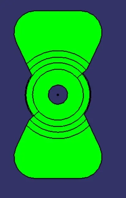
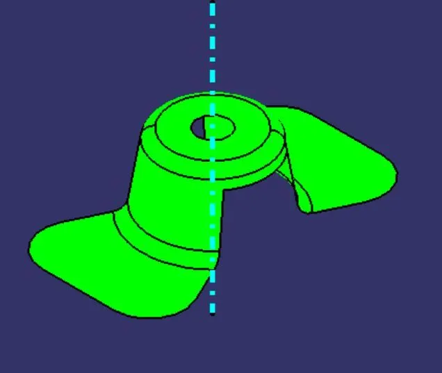
Week 8 - Challenge 1 - Draft Analysis on a Fan Cover
Procedure for Fan Cover
- Step -1:- check the Class-A surface for all joints are connected properly by using the join tool in Join- Healing toolbar or using the Boundary command in the Extracts toolbar
- Step-2:- check the tooling direction of the component in all 3-Axis in my case I took the Z-axis as my tooling direction then Insert a Geometry-set and name as Tooling Axis create a point by using circle Sphere and making a point out of it and drawing a Dummy tooling axis based on the point
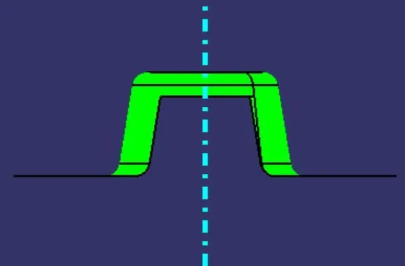
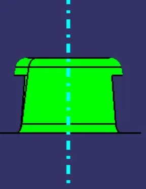
- Step-3:- Check the sidewalls of the component that clears the tooling direction by line command as a bisecting option by expanding the side walls line for extend the side walls use intersect command Repeat the command for both X and Y axis will get the two bisecting lines and use the same command take the x-axis bisecting line and y-axis bisecting as the two lines and form a new bisecting ling and name as Tooling Axis
- Step-4:- Select the object and Tooling axis line and publish them both to create a separate part file
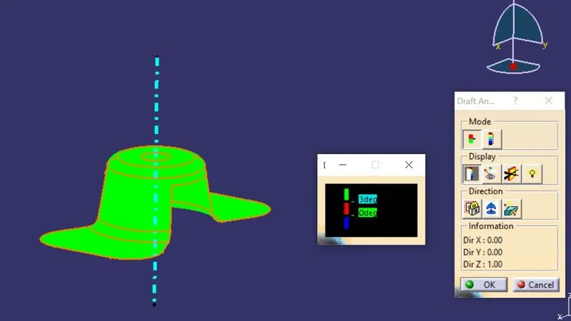
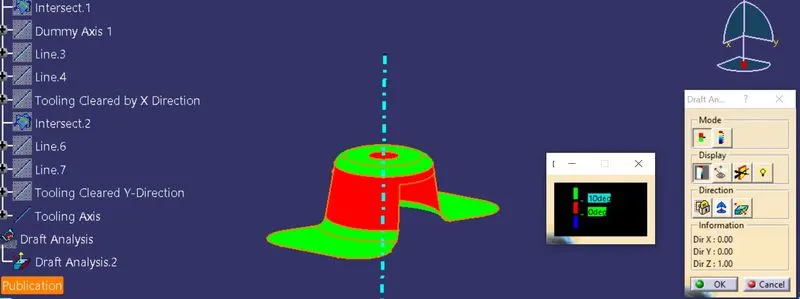
- Step-5:- Check the Draft Analysis of the component for that go to insert Analysis Feature Draft analysis and click command and here opens the draft analysis . after opening the draft analysis use the compass to get the new draft direction ( for Core & Cavity separations ) and make sure that UCS icon Z-axis and component Z-Axis meets at the same line and click on the component and use lock command in Draft analysis.
- Step-6:- In the mode option on Draft analysis command make it as Quick Analysis there will be a popup of two different colors Red & Green. To know the given Draft angles of the component Display option will present in Draft analysis in that use Running Point.
- Step-7:- This is the process of checking of Draft Analysis