Week 7 Challenge
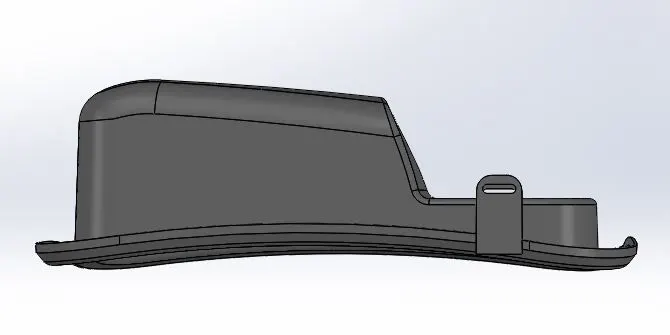
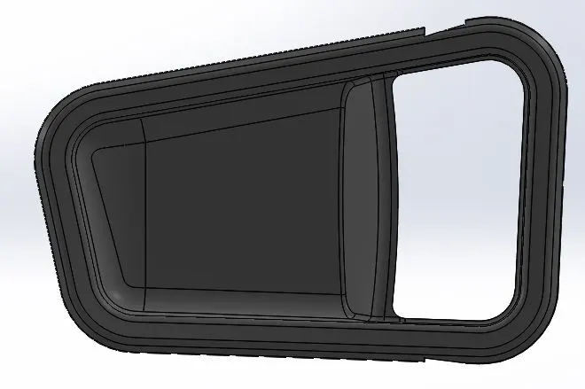
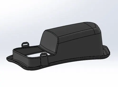
Component
Core
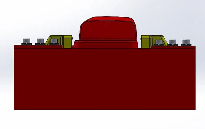

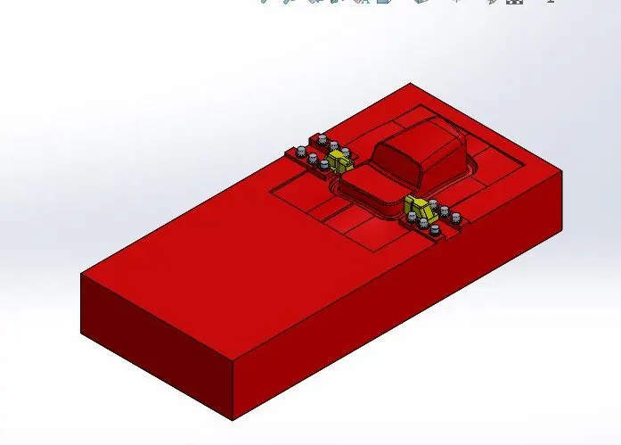
Cavity
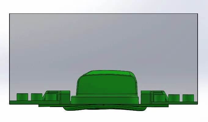
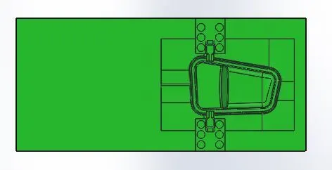
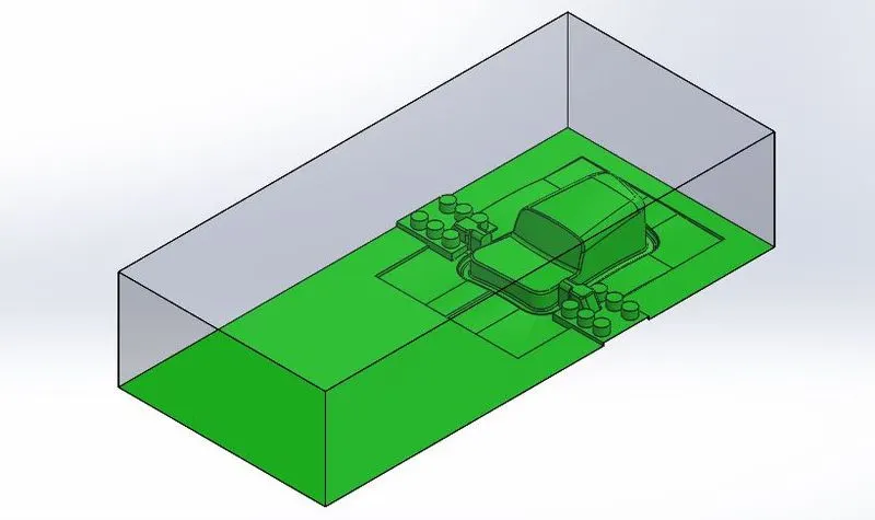
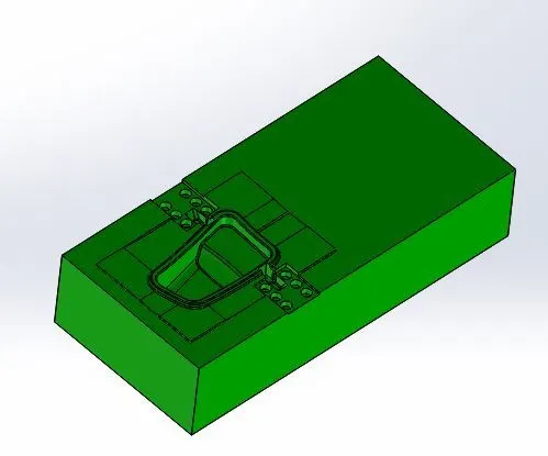
Procedure for Car_Door_Bezel
- Step -1:- Detail understanding of the Car_Door_Bezel for the mold.
- Step -2 After completing the component select the material in my case I am taking the material as ABS and it's having a shrinkage of 0.6%(1.006) component size to be increased by using the SCALE command in mold tools.
- Step – 3 Check the Draft analysis of the component and also finalize the tooling direction for the core and cavity of the mold block. Draft analysis is mainly used for the component and to avoid the difficulty of ejecting the component.
- Step -4 If the Draft Analysis is ok then go for the parting line command in the mold tools command bar. It is the line that separating core and Cavity blocks. If any holes are present in the component use the shutoff surface command in mould -ToolBar then Core and Cavity surfaces are formed.
- Step-5 for the door_ Bezel having 3D surface I am using the ruled surface command in the surfaces command bar for our component not having and any corners for separating radius and straight parts to separate I am using the split-line command in the mold-tools command bar.
- Step-6 uses a ruled surface command that follows the sweep option with a length of 120mm for all the sides for the corners use the surface loft and in the guider, the panel selects the corner of the component the surface-loft will be generated.
- Step-7 joins all the surfaces by using the Knit surface command by selecting all the single surfaces and select the merge in the knit surface.
- Step-8 Copy the merged surface by using the Move/Copy bodies command in the Direct-Editing toolbar and copy the surface
- Step-9 now merge the Core surface and cavity surface with the parting surface separately the core and cavity surfaces are formed to form the mould blocks open the same file as the assembly file and import the door_bezel file to assembly format to create the mould for door_bezel
- Step-10 And also create new two parts files in assembly and name Core steel and cavity steel. And merge all the origins of assembly and part files which meet at screw-path as a mold flow
- Step-11 use a core steel file as the working geometry and draw the rectangle sketch which covers the component with a distance of 50mm from the component and 90mm for the stepper block and 50mm for slider total 290mm width and the length as 630mm for the core main block
- Step-12 to create the 3D surface block make a distance of 30mm from the component with a dimension of 200mm and 25mm far from the top sketch and join the bottom two sketches
- Step-13 make a core-block extrude the block with the surface length of 150mm from the top surface to the bottom part for the main and 3D blocks repeat the same process for the Cavity mold block also
- Step-14 For the slider attachment, we are using the Finger Cam Slider mechanism the attachment is fixed in the Core and the parting will continue on the cavity.
- Step-15 According to the component location slider mainly placed in the Cavity part open cavity steel part separately in that create a reference plane for the slider part and get the sketches of the slider part component using the convert entities to command in the sketch toolbar. By using the sketch and reference plane split the mold by using the split command on the direct-Editing toolbar. we get a separate part for the slider and cavity
- Step-16 For the slider insert component make a sketch on the face of the slider and extrude the till the surface of the component get extruded.
- Step-17 To set the slider with dimensions of the sketch make a rec with a distance of 40mm from the starting point from the slider and the extra part was removed by Extrude cut command feature command bar. and make another rec on the top face with the distance of 20mm vertical distance and 30mm horizontal distance and Extrude till the lower surface.
- Step-18 Copy the slider by using the direct editing command and subtract the object from the cavity block. and close the extra space by using extrude command for closing the inner cuts if the slider use move/copy command in the Direct-Editing command bar.. and repeat the same process for the second slider.
- Step-19 After creating slider separate part file for that open cavity steel file and select the slider in solid bodies right click on it the go-to insert a new part and save a new file in preferable And create a new part file in assembly and insert new the file in it by selecting insert command to features to import the file then the separate slider part file is created. and repeat the same process for the other slider.
- Step-20 Use some filets for the slide and core and cavity to avoid sharp edges and the economic efficiency of the component for manufacturing.
- Step-21 Now open the core file and make a path of the slider import the fie in core part and use combine command in the direct editing ad separate the component for the excess removing of the component we extrude cut command then the path was created.
- Step-22 Taking slider endpoints as a reference create Guideways for the slider with the width of 12mm and do the same operation for another slider.
- Step-23 For creating holes and washers create an apart file in assembly and name as washer and edit file take the top plane as a reference plane start sketching in it. Washer dia of 16mm make the possibility of sketches in one side and use mirror command to get the same sketches in the other side then open the file in separate part file and extrude the sketches with 3mm for the bolts the head dia of 11mm extrude 7mm high for the sank of bolt dia 6mm and extrude depth of 22mm to place the bolt in the washer use sketch pattern command
- Step-24 To get the same patterns in the core block edit the core steel file use the Hole-Wizard command to get the screw in hole wizard spot a position in the bolt position will et the exact positioning of holes and repeat the same process for the opposite side
- Step-25 At the final calculate the slider travel and add the extra connections for it to calculate the slider travel select the measure command in Evaluate toolbar select the two points we will get the distance b/w two points. and add the connecting pinpoints for it. Repeat the same process for the opposite side
- Step-26 This process for Mold Design in SolidWorks