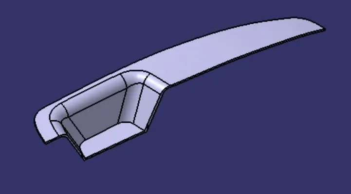
Week 8 - Challenge 3 - Switch Bezel Design
Procedure To Create Class-B & Class-C & Draft Analysis of Base Bracket
Step -1: - check the Class-A surface for all joints are connected properly if any surfaces are required to join use the join tool in Join- Healing toolbar or use the Boundary command in the Extract toolbar
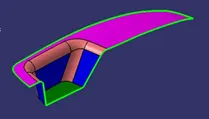
Step -2: - check component in all 3 Axis the component. In which direction component can clear all the features in the tooling axis. In my case, I assumed Z-Axis is the tooling direction. And check the line Bisection method for 1 side and other side use sketch as the line and give some an angle of 30 and create a tooling axis for the component and use the line command and create the line using bisecting option and create a tooling axis of the component in the Z-axis.
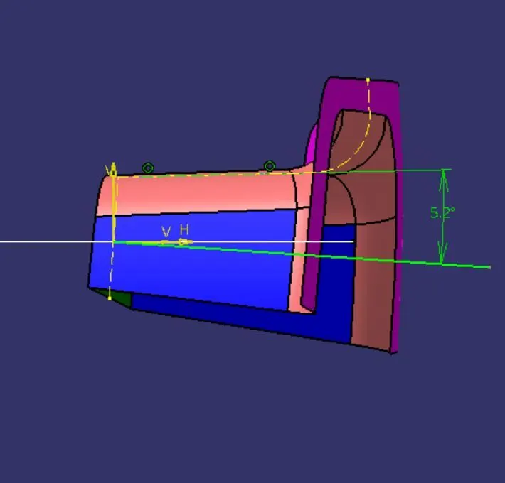
Step -3: - check the component Tooling axis of the component and the side surfaces are visual then the Tooling Axis is correct this is for the class -A surface ones all the component was created then if any changes are required we can adjust from there Tooling Axis of the component was created.
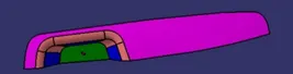
Step -4: -create the Geometry set and name as Constructions For Class B & C Surfaces add the Tooling axis to that set and Publish the class -A and Tooling axis. And insert the geometry set and name as B-surface creating and start creating the B-surface for the side parts and Extract it and then Antrim the parts and extrapolate the surface and Trim the unwanted extra surfaces and Offset the surface at 2.5mm below the class-A.

Step -5: - Repeat the same process for the other surfaces and name the surfaces as Base, Top Hand Rest, and at the final step trim and join all the surfaces at the separate geometric set for the clear identification of the surfaces and name the surface as Final Surfaces.
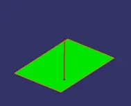
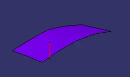
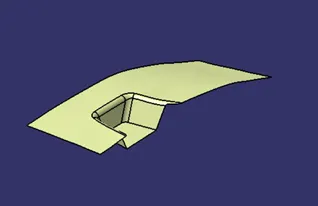
Step -6: - Next step is to create the C-surface to connect the Class -A&B for that crate a new geometric set and name as C-Surface Creating and use multi-Extract command and sect the class-A surface edges and create the surface end lines and create the smooth curve with and deviation of 0.001mm to reduce the connecting of the points and for the visual purpose, to get the final surface use sweep command with a draft angle of 30 to create the sweep select the curve and tooling axis as Draft direction and select ok, repeat the same process for the other side to get the c-surface. And use Extrapolate the surface to extend the surface were to require the extension and trim the unwanted surfaces.
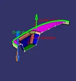
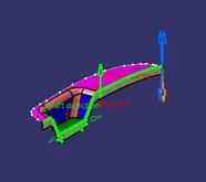
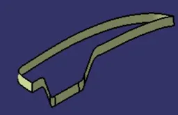
Step -7: - To join and trim all the surfaces into a single surface to get a complete component for insert a geometrical set and name as Final Trims & Joints and get the complete required Surfaces
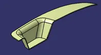
Step -8: - To make a completely solid part file go to the part Design workbench and use the Close Surface command and select the surfaces that joined into a single component and select ok the part was created into solid.
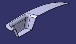
Step -9: - After creating the part file use the Draft analysis command of the part using the same Tooling Axis for the Draft analysis. To Assess the draft analysis command, go to Insert Analysis Feature Draft Analysis. Draft analysis interface will open and use compose option and select the UCS and fix the axis to the component. And check the draft position correct or not if it is in the wrong direction change to inverse the draft direction. If any changes are required for the changes in the walls Draft angle adjust the sketch to get the perfect Draft angle. Hence the final part was completed with solid feature and Draft analysis.
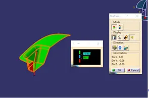
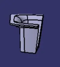
Views of the Switch Bezel
Front-View
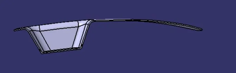
Side-View
Top-View
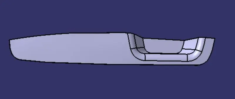
Iso-view