Wiring harness design in CATIA V5 - 3D modeling Week 5 & 6 Challenge
Aim:
- Route two electrical harnesses per the given layout and interconnect them as a single harness assembly
- check for bundle continuity, and bundle warnings, and then provide annotations for the final harness assembly.
Objective:
- The objective of this project is to first route the two Harness A and Harness B as per the given harness layout.
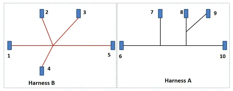
The electrical connectors are represented by numbers in the above figure. There are 8 different types of connectors at 10 different locations.
2. Bundle continuity has to be checked for the two created harnesses.
3. After the two Harnesses are created, the next objective is to have them interconnected electrically.
4. Check for bundle warnings in Harness A and Harness B.
5. Add annotations to all the connectors in Harness A and Harness B.
PROCEDURE
Step-1:
Define all the electrical connectors geometrically and electrically so that they can be used in the wiring harness.
Electrical definition of Connectors for Harness A:-
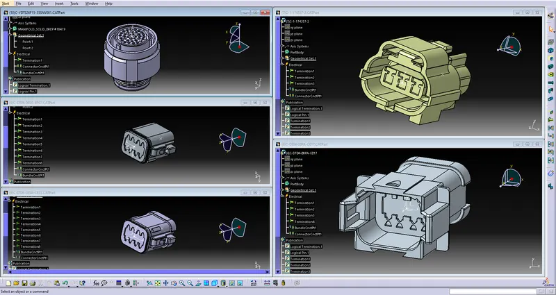
Electrical definition of Connectors for Harness B:-
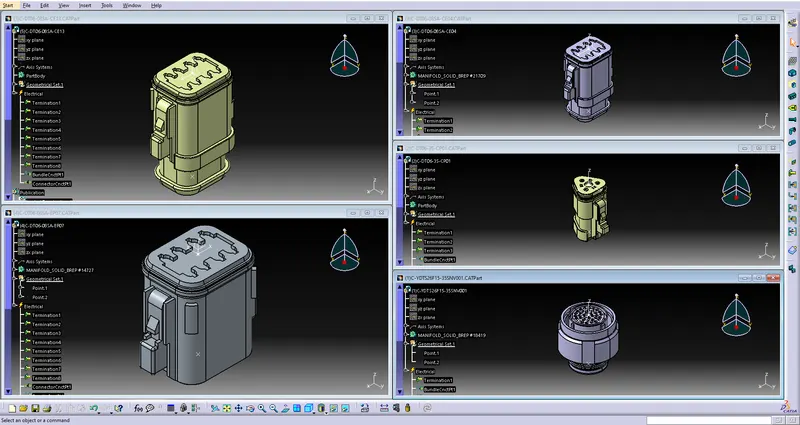
Step -2:
After electrical definitions, we have to create catalogue for these connectors, as follows
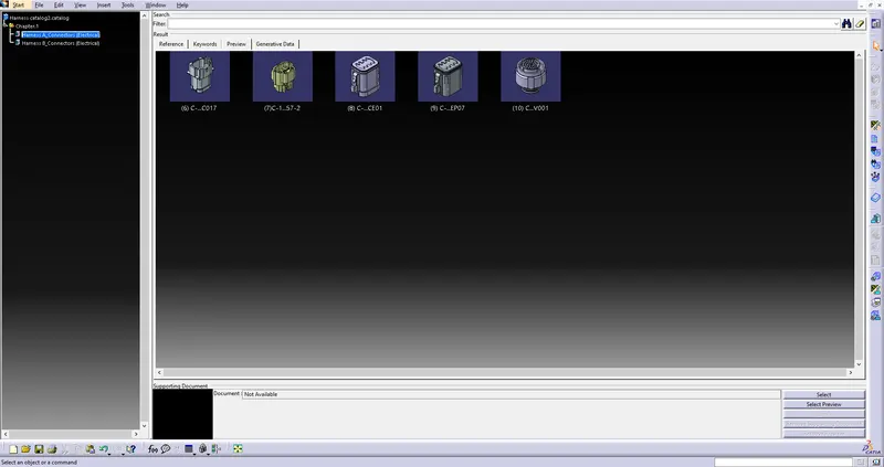
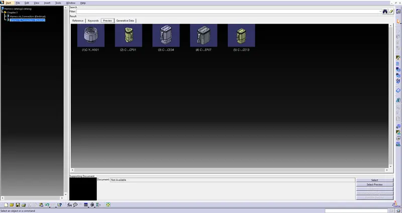
Step-3:
Now, we position the respective given connectors for corresponding harness, from Catalog we created, in the Electrical Harness Assembly workbench, as follows:-
For Harness A:-
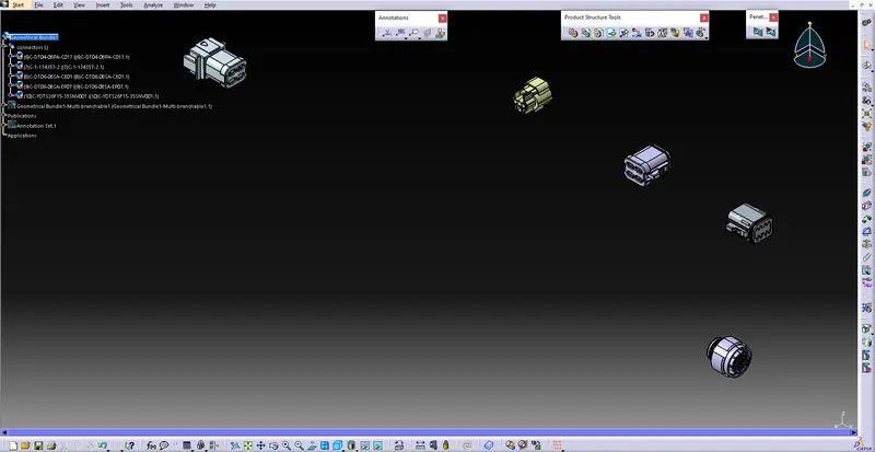
For Harness B:-
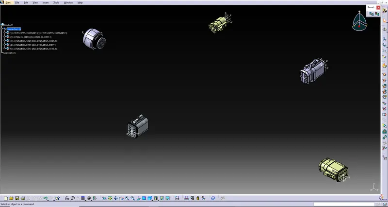
Step-4:
Now, we have to rout the harness between connectors as per given layout, as follows:-
For Harness A:-
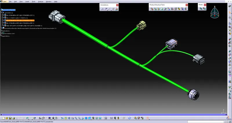
For Harness B:-
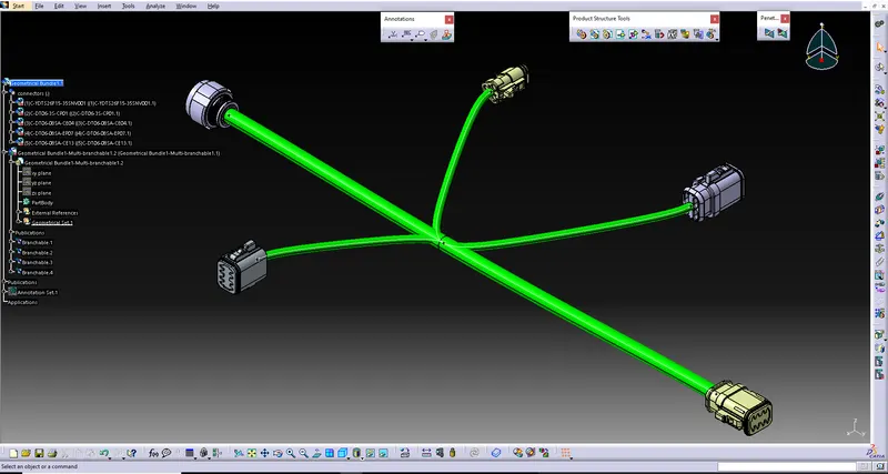
Step-5:
Now, we have to check for bundle connectivity, from network assistant option in Electrical Harness Flattening workbench.
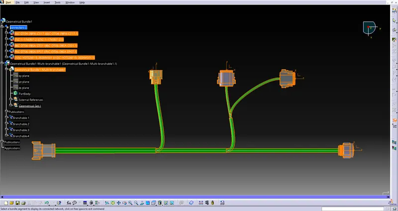
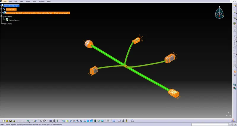
Step-6:
For adding Annotation to the connectors, we have to first select reference plane for annotation from view from reference option in Annotation tab inside Assembly workbench.
Then we have to choose Flag note with leader option for annotation, and choose where you want annotation.
For Harness A:-
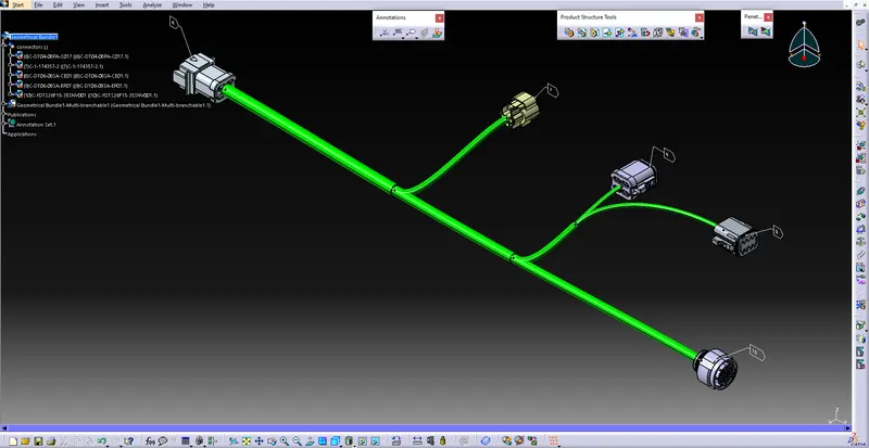
For Harness B:-
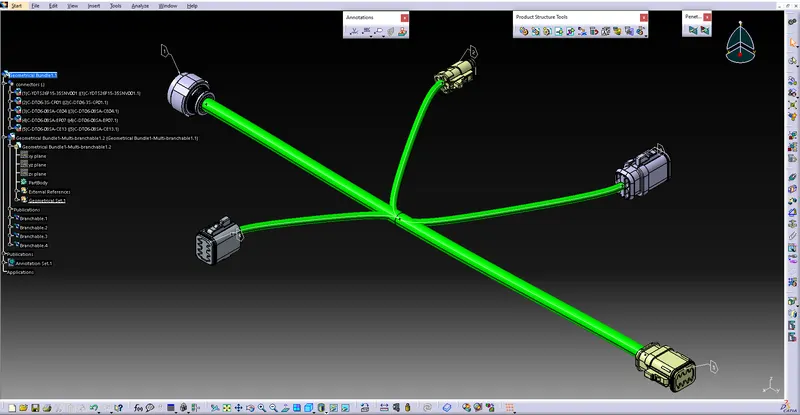
INTERCONNECTION:
Firstly, we open a new product file and insert existing component as both wiring harness.
Then, we have to connect the connectors by selecting connect electrical device from Electrical Assembly Design workbench.
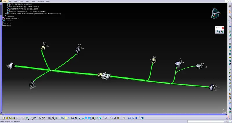
BUNDLE WARNING :
Checked for bundle warning and solve it
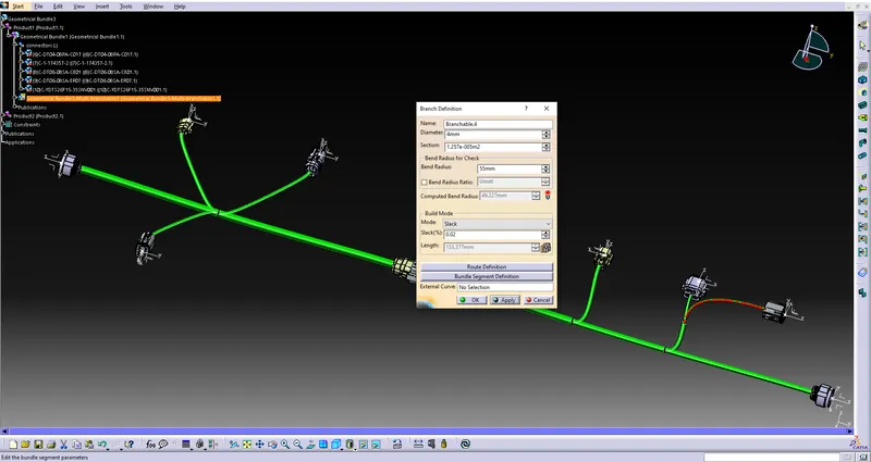
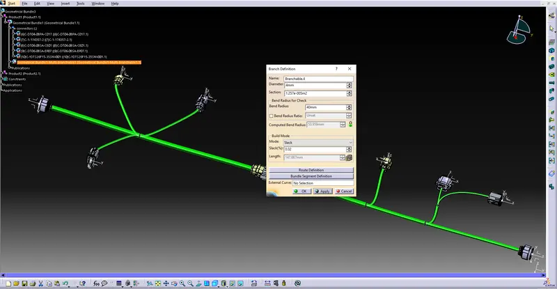
First, it was indicating on the routing and Branch Definition tab for bundle warning, because the bend radius was not acceptable.
So i rectified, the bundle warning by giving appropriate bend radius.