Wiring harness design in CATIA V5 - 3D modeling Week 5 & 6 Challenge
AIM:
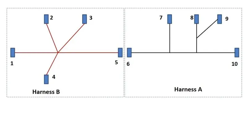
- To create a Wiring harness assembly and route the harness as per the given layout.
OBJECTIVE:
- To electrically define all the parts provided.
- To create wiring harness assembly and route the harness as per the given layout.
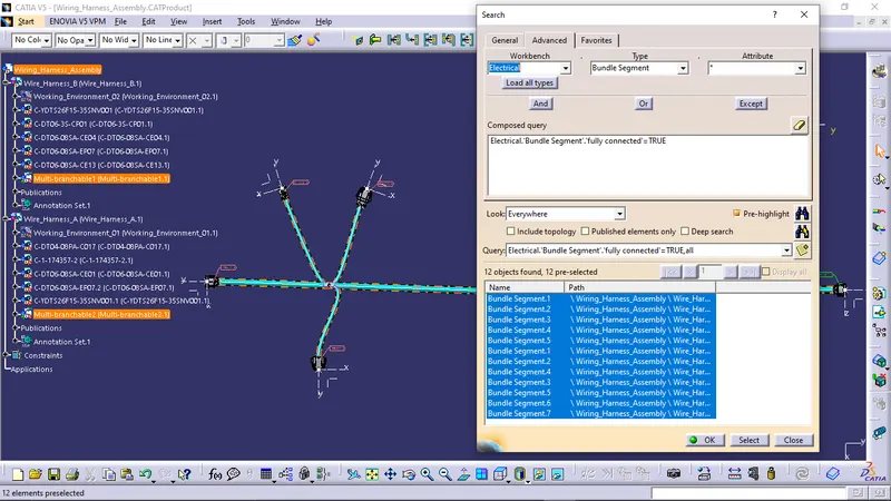
- To check for the bundle segment continuity.
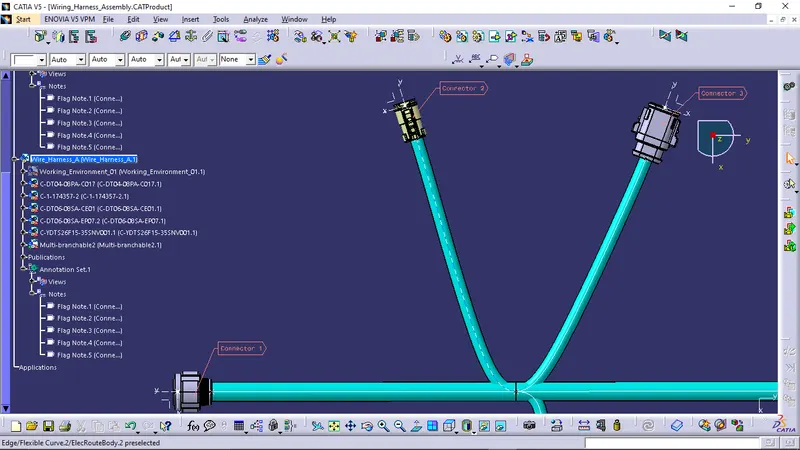
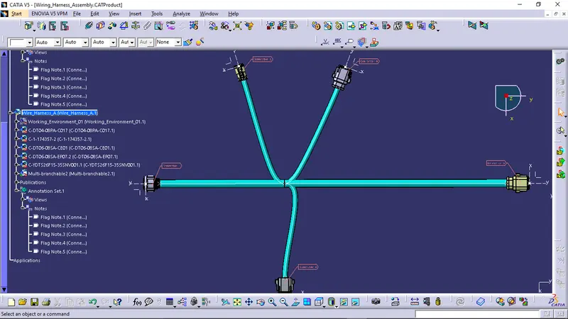
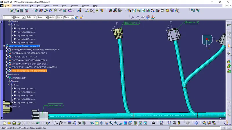
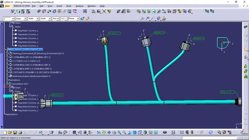
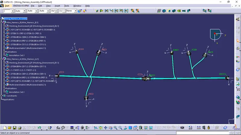
- To add annotations to all connectors.
- To check for bundle warning.
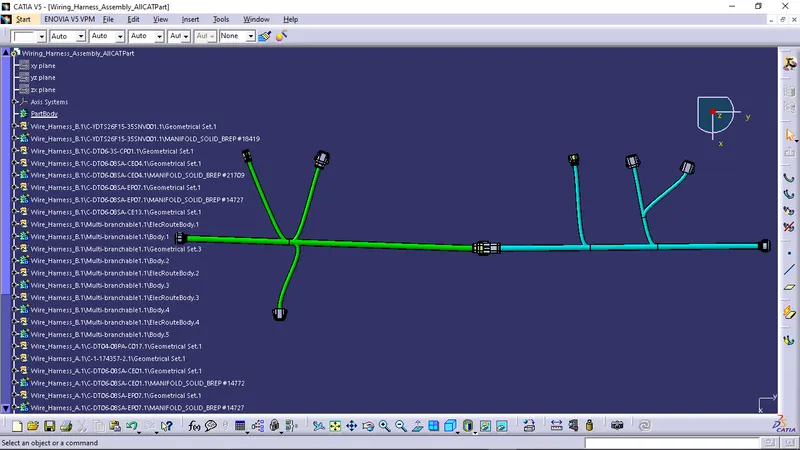
- To generate the CAT.part of the complete wiring harness assembly and convert it into .igs format.
SOLUTION METHODOLOGY:
Step - 1:
- To download all the 3-D CAD data required for the above assignment and save it in the desired folder.
Step - 2:
- To identify the connector side and the bundle side and create points and axis system at the mid-point of the mating surface.
Step - 3:
- To navigate to the Electrical Part design workbench and define the electrical properties of the connector by:
- First defining the part body as a connector.
- Then defining the connector connection point.
- And then defining the bundle connection point.
- The above steps should be followed for all the Connectors to electrically define them and use them in the wiring harness assembly.
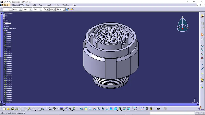
CONNECTOR - 1:
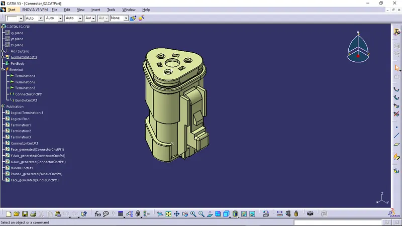
CONNECTOR - 2:
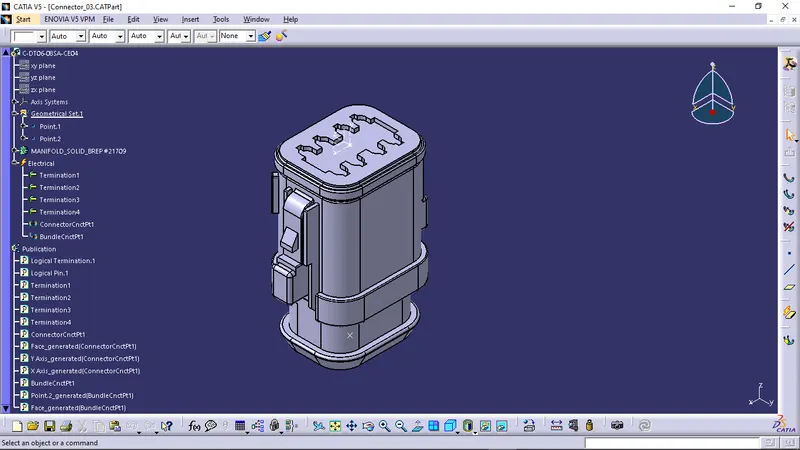
CONNECTOR - 3:
CONNECTOR - 4:
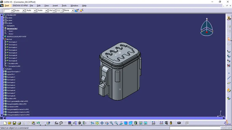
CONNECTOR - 5:
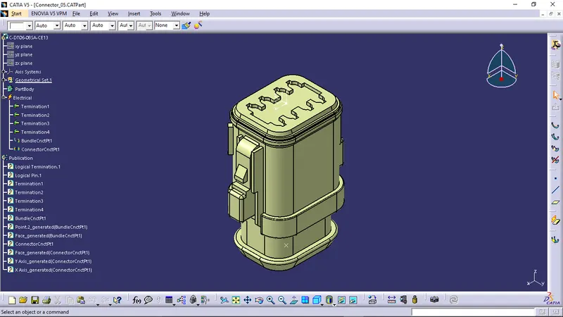
CONNECTOR - 6:
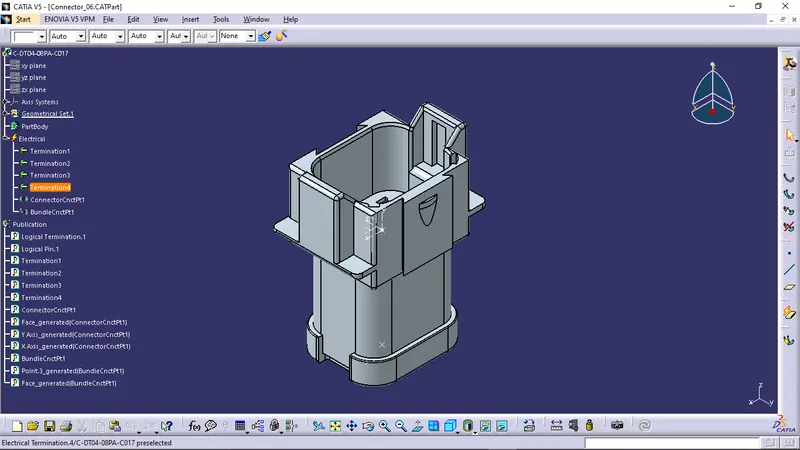
CONNECTOR - 7:
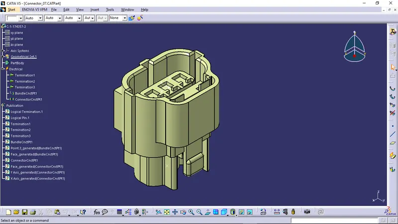
CONNECTOR - 8:
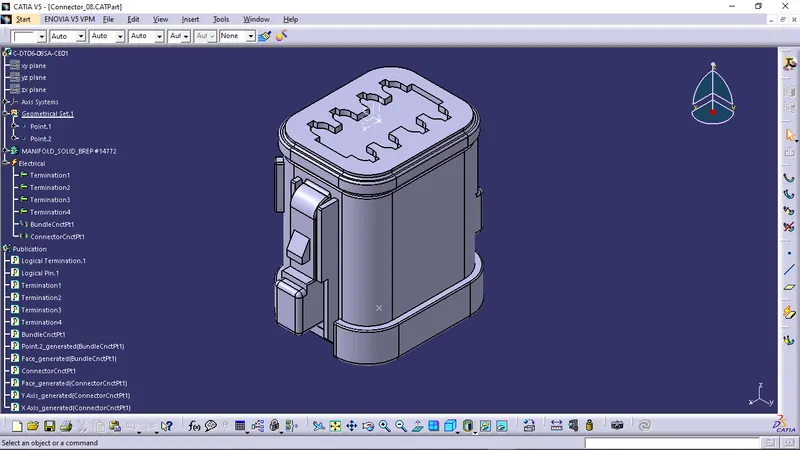
CONNECTOR - 9:
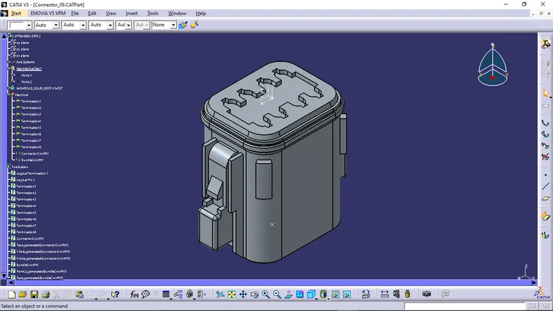
CONNECTOR - 10:
Step - 4:
- Create a working environment platform to place the connectors easily, smoothy and in a proper orientation.
WORKING ENVIRONMENT FOR WIRE HARNESS A:
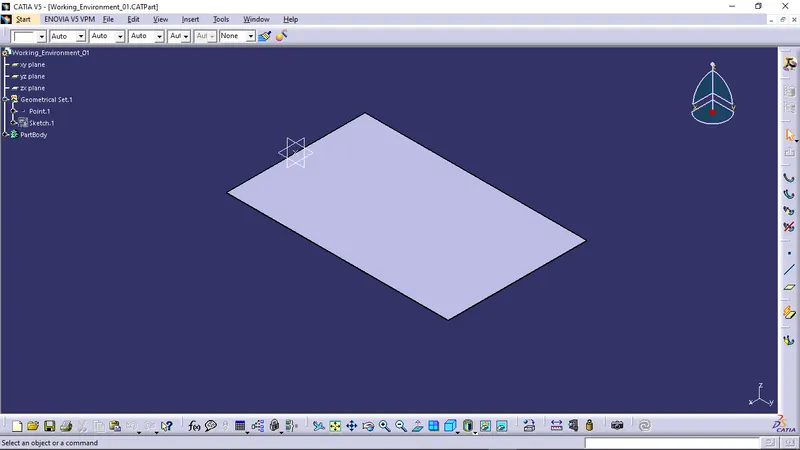
WORKING ENVIRONMENT FOR WIRE HARNESS B:
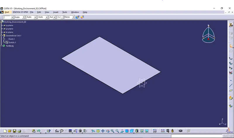
Step - 5:
- Create a new product for Wire harness A layout.
- Add all the connectors that are required for the harness layout and also add the working environment.
- Place all the connectors in their respective positions according to the given layout.
WIRE HARNESS A LAYOUT:
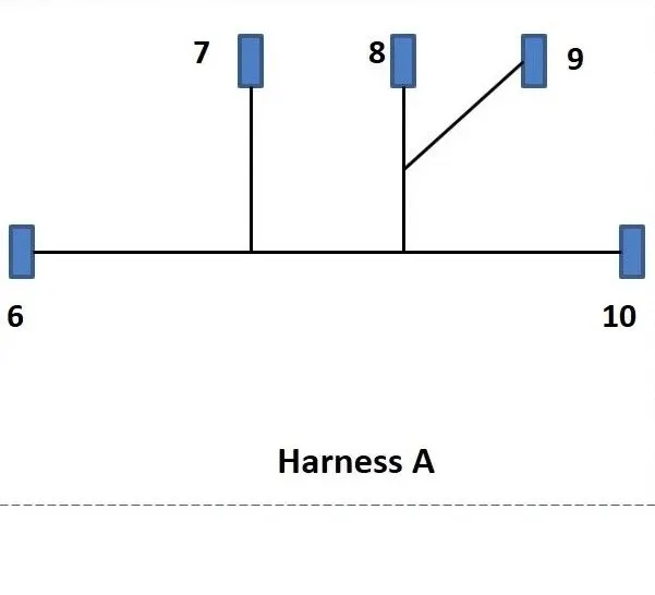
Step - 6:
- Create the wire routing according to the above layout.
WIRE HARNESS A ROUTING:
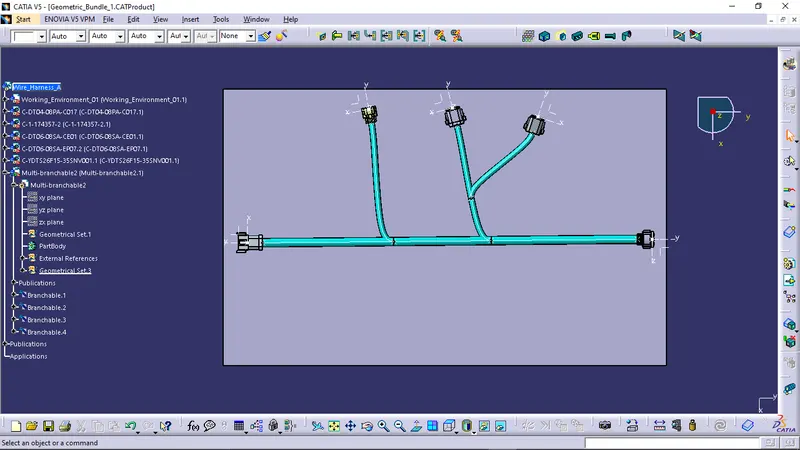
Step - 7:
- Checking the continuity of the bundle segments:
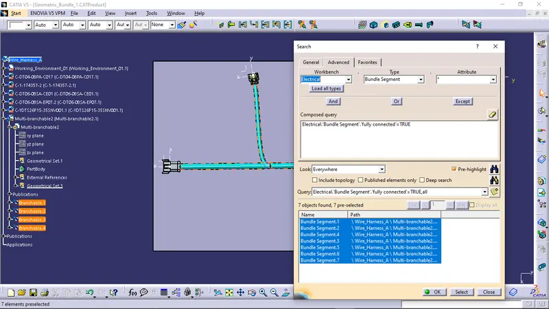
Step - 8:
- Create a new product for Wire harness B layout.
- Add all the connectors that are required for the harness layout and also add the working environment.
- Place all the connectors in their respective positions according to the given layout.
WIRE HARNESS B LAYOUT:
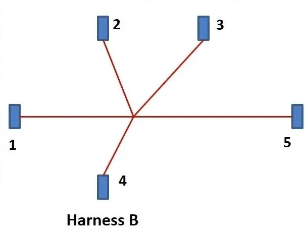
Step - 9:
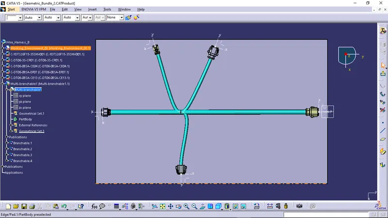
- Create the wire routing according to the above layout.
WIRE HARNESS A ROUTING:
Step - 10:
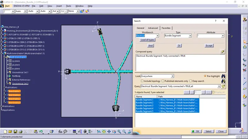
- Checking the continuity of the bundle segments:
Step - 11:
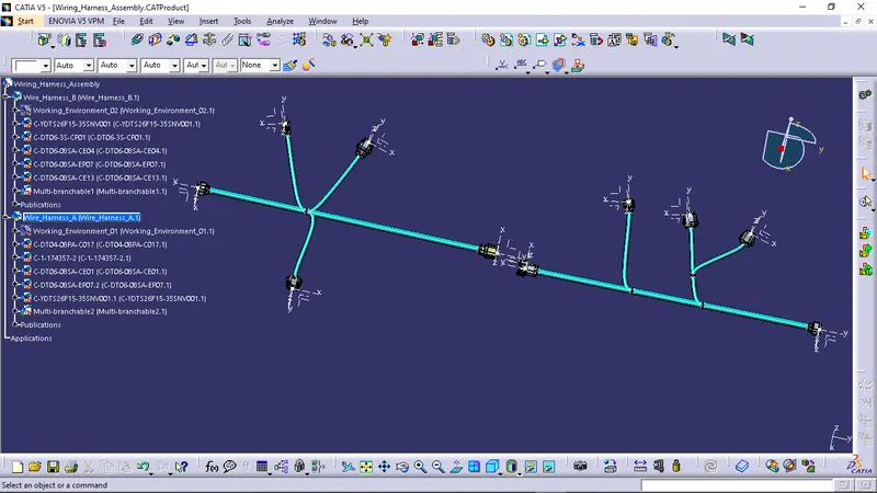
- Creating a new product file to assemble both the wire harness A and B.
- Add both the Wire harness A and Wire harness B product file to the main Wire harness assembly file.
Step - 12:
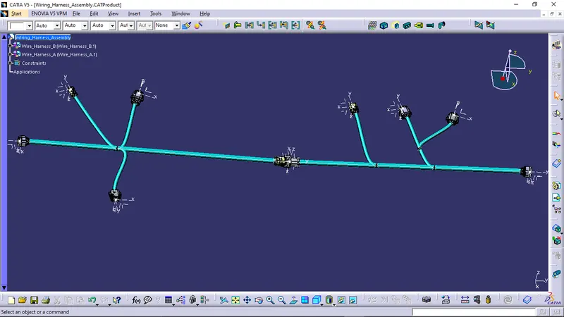
- Navigate to the Electrical Assembly Design workbench.
- Select the 'connect electrical devices' and select the connector 5 of wire harness B and connector 6 of wire harness A.
ADDING ANNOTATIONS TO ALL CONNECTORS:
CHECKING FOR BUNDLE CONTINUITY:
GENERATING THE CAT.PART OF THE WIRING HARNESS ASSEMBLY AND CONVERTING INTO .IGS FORMAT:
CONCLUSION:
- From the above assignment we learnt how to create wiring harness assembly, wire routing and how to connect two separate wire harness assembly.
- We also learnt how to check the bundle continuity, give annotations to the connectors.
- We also learnt how to solve the bundle warning with different methods.
- We also learnt how to convert a CAT.product file to a CAT.part file.