Wiring harness design in CATIA V5 - 3D modeling Week 5 & 6 Challenge
Steps: a) Mechanical Part Design for the connectors,adding Geometrical parameters like Bundle Point and Connector Connection Point.
b) Defining the Connector and defining connector point and bundle point for electrical Design and Storage the device using the no. of terminals(8,3 and 37) it has.
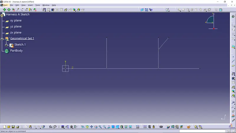
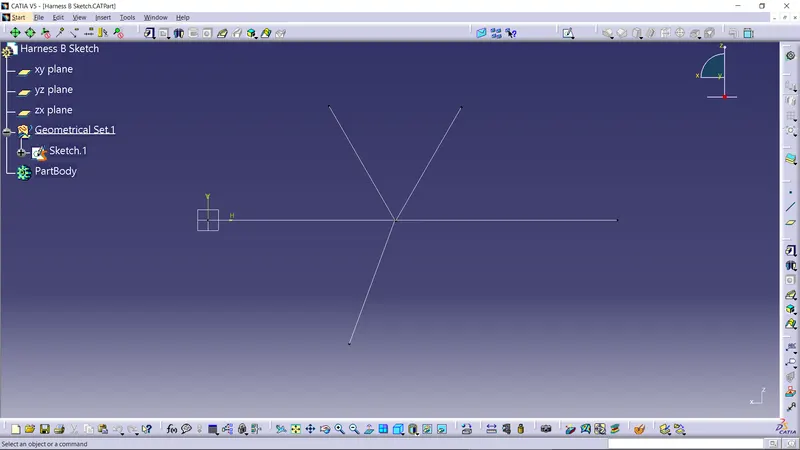
c) Draw the sketch for harness A and B for positioning of all the connectorns for creating the Haarness assembly
 |
|
D) Now we need to make a harness assembly A and B. So, use electical harness assembly workbench and position them at their respective positions and define he products as geometric bundle.
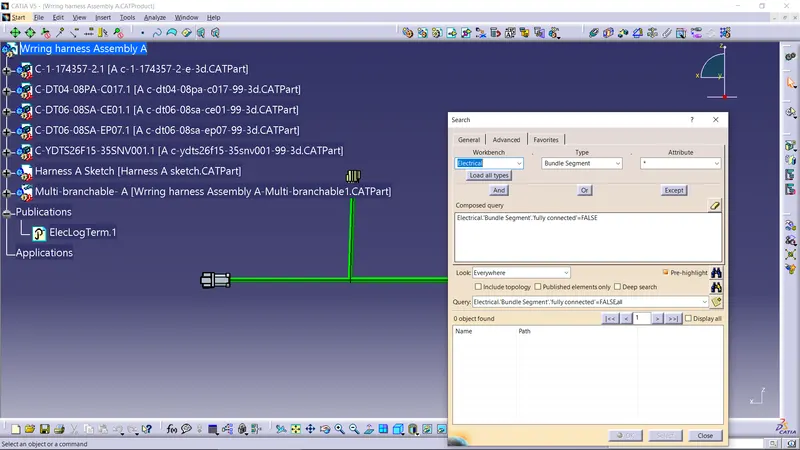
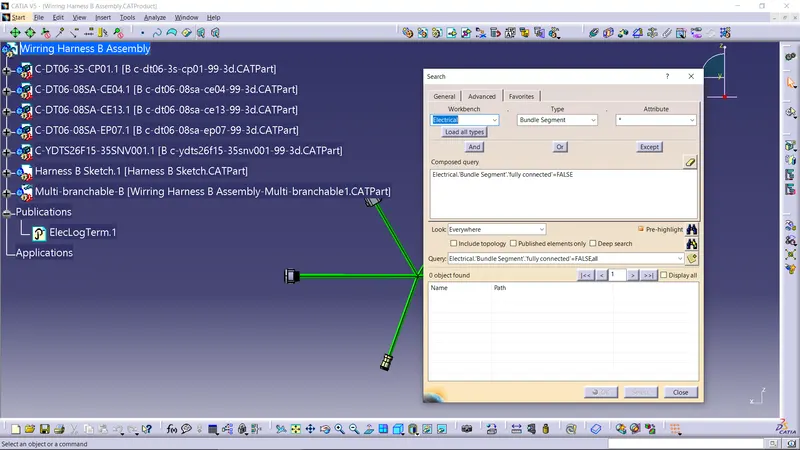
E) Now, by using Multi-Branchable document command and by creating branch point as required create all the bundle segments.
F) Once bundle segments are dreawn, we need to Check the bundle Continuity for that we need to do to edit option> Search>Advance >Workbench(Electical)> Type(Bundle Segemnt) > Attribute(Fully Connected).
G) Now, we need to put the 3D Annotations to both the harness assembly for all the connectors.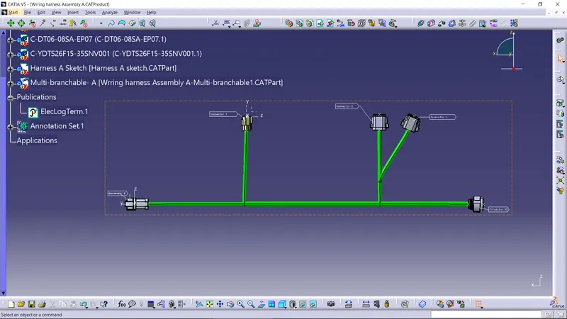
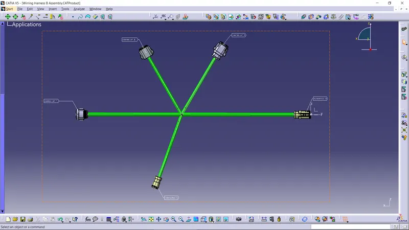
H) After labelling we need to connect both the harness assembly so we need to make a product. So, connect them in electrical Assembly design workbench by using electrical connectivity command update it and save the file.
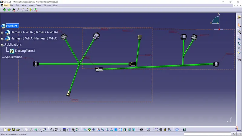
I) Switch to Assembly Design Workbench and generate the CAT Part.