Project 2
Step-1: By using the Bacdoor CAD Data create a part. Now to Create a wire harness routine create a Backdoor Context Assembly file and use a Bacdoor part as one of the sub product of Context Assembly. Create a sub product to create a geometric bundle for Backdoor.
Step-2: Now by creating a geometric bundle, Start Mechanical Part Design for the connectors, Storage the device using terminals, adding Geometrical parameters like Bundle Point and Connector Connection Point or the connectors can be used which are available in the connector catalog. same follow for the different clamps and Clips which will be required for creating the Geometric Bundle.
(Connector Used: c-1563689-1-4P and a 12-Pole Interconnector, P-Clamps and Fir Tree Clips )
Step-3: Position the Connectors, Clips and Clamps at their respective position and their requirement for creating the geometric bundle and to add bundle segments.
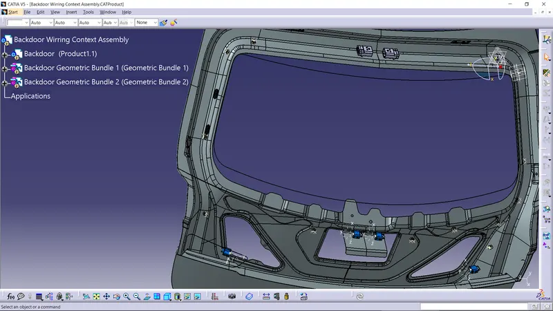
Step-4: After positioning the Connectors, Clips and Clamps at their respective position and their requirement. we need to create two different geometric bundle which will have two different Multi-branchables. Open the Electrical Assembly Workbench and start adding the bundle segments Inter Connection Connectors to different connectors for Tail Light and Plate Light by using P-Clamps and Fir-Tree Clips.
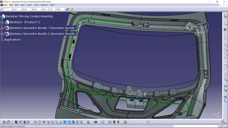
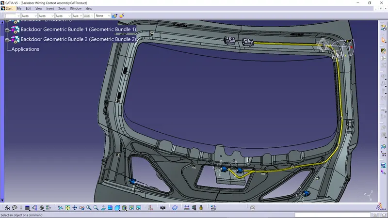
Step-5: After creating the bunle gements check the interconnections whetehr all the Bundle Segments are linked or not.
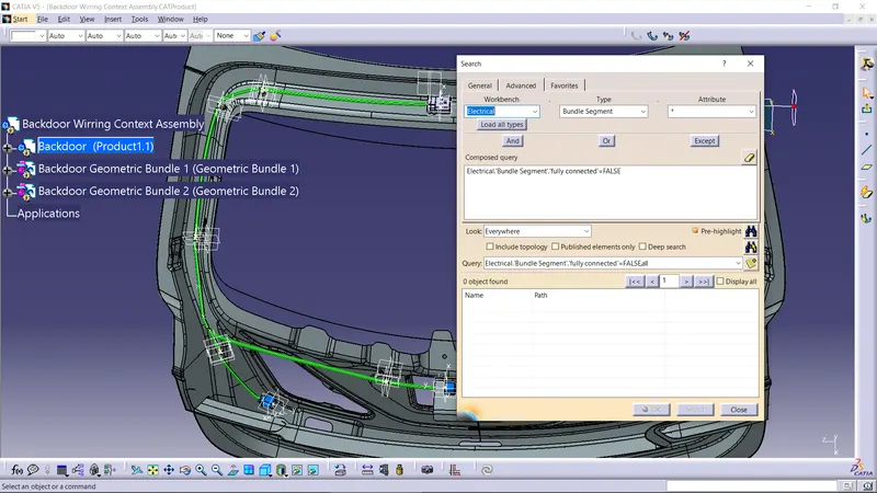
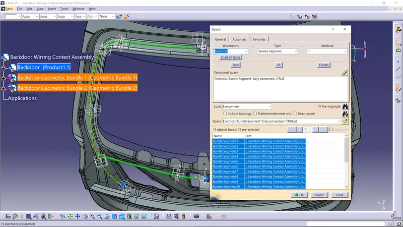
Step-6: After Checking by using Protective covering coomand from Electrical Aeembly Worbench start adding the Rubber Tapes Like PVC coating(Blue) or the cotton Coating(Brown) by keeping some distance at Start and Extremity.
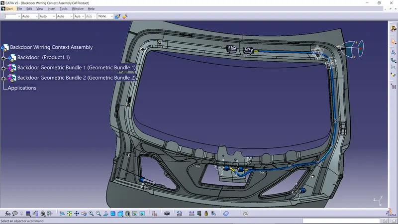
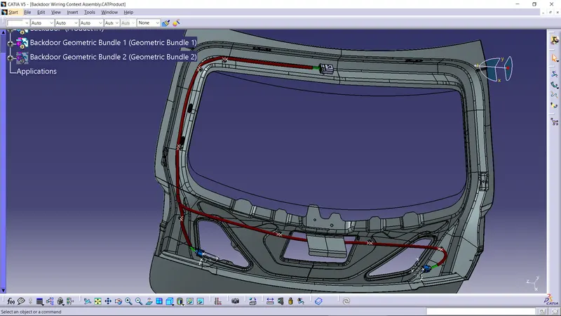
Step-7: Add the Corrugated tubes as a protective Covering for both the Bundle segments. 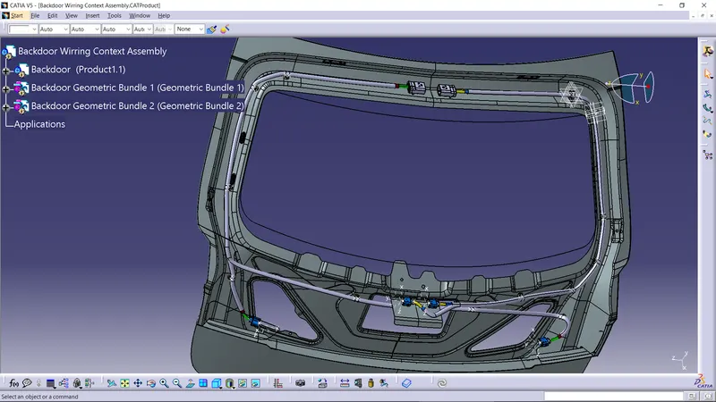
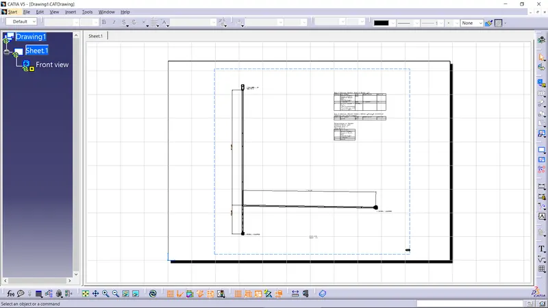
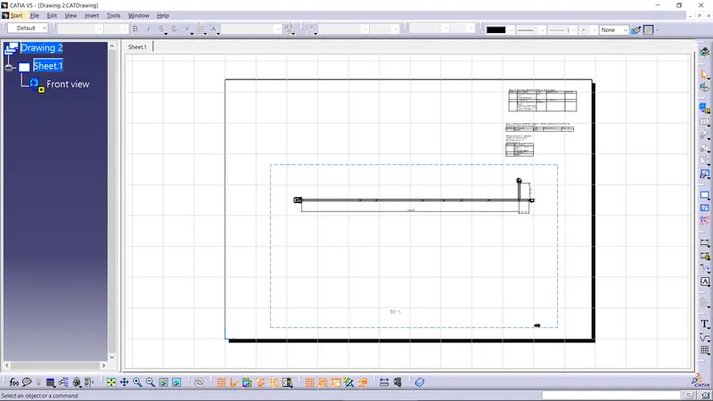
Step-8: Now the Assembly is complete,Save the Context Assembly. Now, by using Electrical Flattening Workbench Flatten both the bundle segements separatelty and by using different comands like Arrange Junctions, bend, Rotation, and Quick Roataions do the modifications accordingly.(In this the Clis and Clamps and protrctive covering are not visible because of software problems)
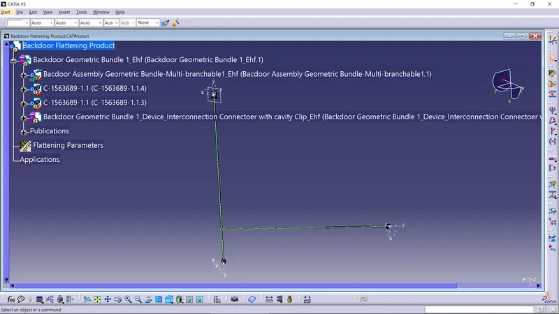
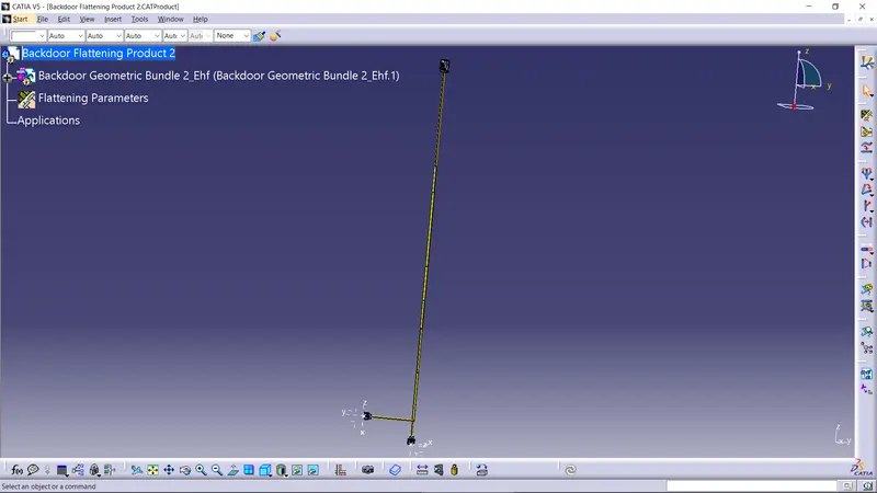
Step-9: Now crete a new file as a Drawing select a front view command and by selecting the prouct as a geometric bundle and by selectimg the Plane. Add the Bill of Material by using sheet background from EHf file of Flatten Bundle Segment.