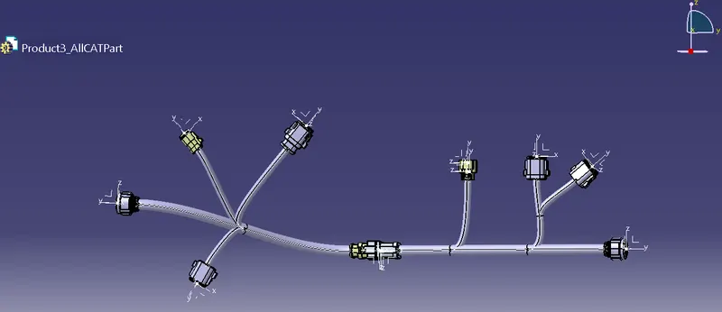
Wiring harness design in CATIA V5 - 3D modeling Week 5 & 6 Challenge
Wiring harness design in CATIA V5 - 3D modeling Week 5 & 6 Challenge
Aim:-
Q1. Route the following harness layout in the Electrical workbench. Assume harness bundle diameters. Use the connectors provided. After completion of routing,
- Check the bundle Continuity. Add a snap of the result in the submission
- Add annotation to all connectors. Make assumptions for annotations like connect 1, 2, etc
- Check for the bundle warning. Add snap.
- Generate CAT.part of harness assembly and convert it in. igs format.
Click here for CAD data and routing mapping data
Solution:-
Initially, all the connectors are electrically defined using the below steps -
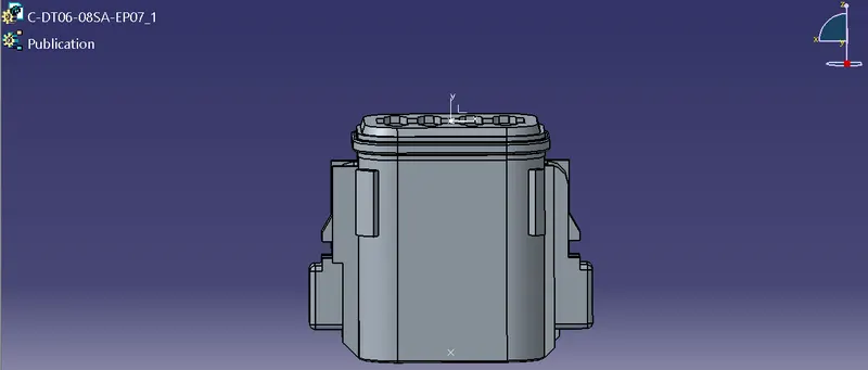
- Download Connector 3D (from the given google drive link)
Mechanical Part Design
- Defining Geometrical Parameters (Points and Axis system)
Electrical Part Design
- Define part as Connector
- Define Bundle Connection Point
- Define Connector Connection Point
A catalog is also been created and all the electrically defined connectors are added to the same to use in the Geometrical bundle using Catalog Browser.
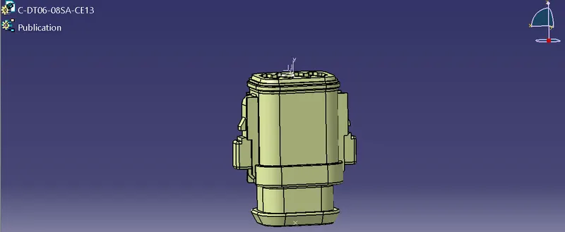
Harness B Connectors
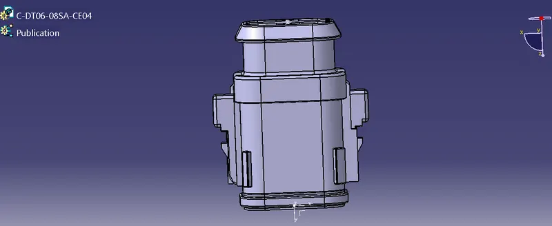

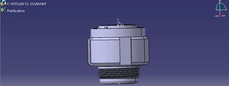
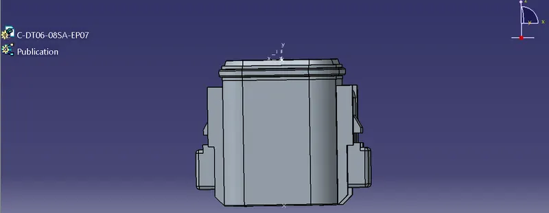
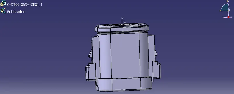
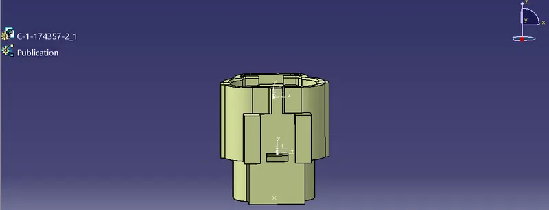
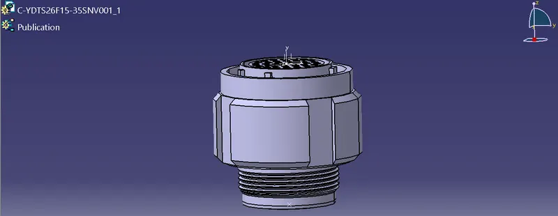
Harness A Connectors

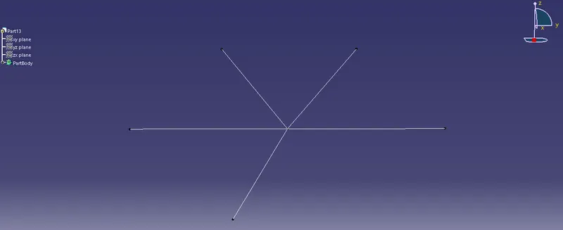
Sketch of Harness B
Sketcher (Mechanical Design)
- Line
A sketch is created for the harness context assembly from Sketcher. Line command is used to create the sketch with the required parameters.
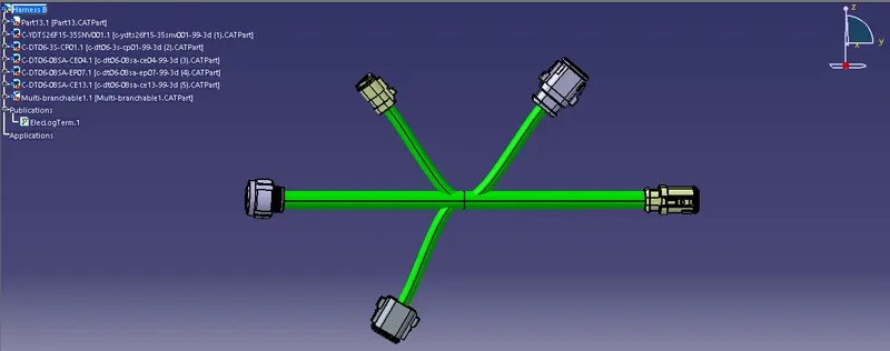
Geometrical Bundle Assembly of Harness B
Mechanical Assembly Design
- Catalog Browser
All the electrical connectors are loaded in the geometrical bundle using Catalog Browser from their catalog. Manipulation, Snap, and Compass are the tools used from the mechanical assembly design workbench to place the connectors at the desired positions of the sketch.
Electrical Harness Assembly
- Geometric Bundle
The geometric Bundle command is used to electrify the geometrical bundle.
- Multi-Branchable Document
The multi-Branchable Document command is used to initiate branches for the electrical components using Branch Definition.
Electrical Harness Installation
- Branch Definition
Branch Definition command is used to define the branches between the objects. A branch diameter of 15mm for the main tree is taken and for the sub-branch, it is 10mm. Bend Radius is 1.4 for the routing, and in Build Mode, 0 Slac is considered for the entire routing.
In Route Definition, objects/components are selected for which the branches are to be made.
- Add Branch Point
Branch points are created from the main branch using Add Branch Point command. The branch is selected for which the branch point is to be created and distance is defined for the branch point. New branches can be created through the same branch point.
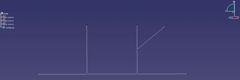
Sketch of Harness A
Sketcher (Mechanical Design)
- Line
Geometrical Bundle Assembly of Harness A
Mechanical Assembly Design
- Catalog Browser
Electrical Harness Assembly
- Geometric Bundle
- Multi-Branchable Document
Electrical Harness Installation
- Branch Definition
- Add Branch Point
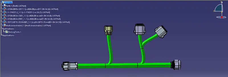
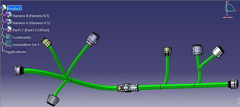
Product or Harness Assembly of Harness B and Harness A
Electrical Assembly Design
- Connect Electrical Devices
Interconnection between the two harnesses (Connectors 5 & 6) is made using connect electrical devices in the electrical assembly design workbench. Initially, placement of both the geometrical bundle assembly and axis orientation is done for proper connection.
Bundle Continuity
- Edit
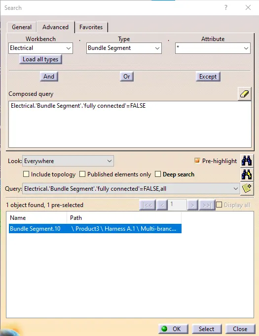
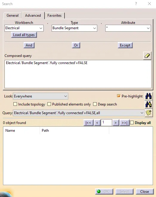
Bundle continuity is checked through edit and below are the false connection found for bundle segments 9 & 10. These are rectified by deleting the segment and routing the new bundle segments.
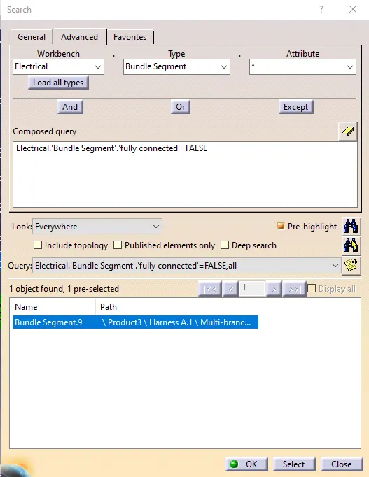
Above bundle, segment errors are been resolved.
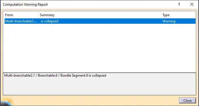
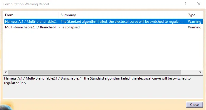
Bundle Warnings
These are the warnings that occurred while resolving the false bundle connectivity.
Annotation to all Connectors
Mechanical Assembly Design
- View Creation
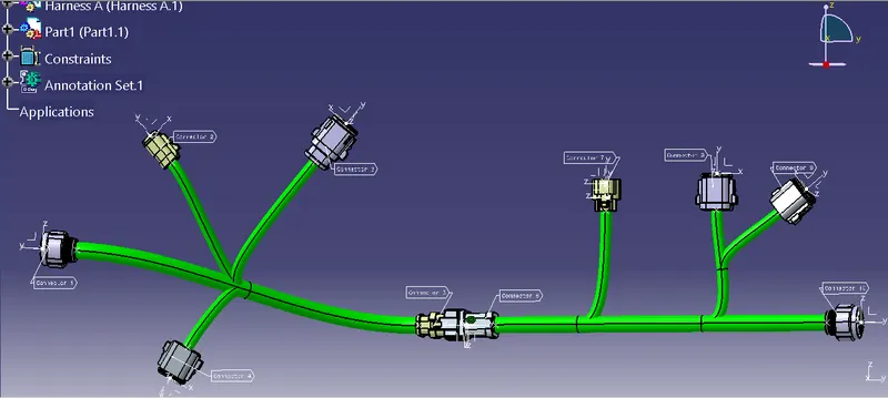
The plane is created for any side of a connector for the annotation and also the name for the annotation set is defined. The annotation will reflect on the same side of the connector where the plane is created.
- Flag Note with Leader
Flag Note with Leader is used to write the annotations for the connectors.
CATPart of Harness Assembly
Mechanical Assembly Design
Tools
- Generate CATPart from the Product
Generate CATPart from Product is used from Tools to convert the CATProduct to ALLCATPart and then the same file is saved using save as in .igs format.