Week 2- 2R Robotic Arm Challenge
2R Robotic Arm Challenge
AIM:-
To write a program in Matlab to simulate the forward kinematics of a 2R Robotic Arm. Also to create an animation file of the plot.
Principle:-
Forward kinematics refers to the use of the kinematic equations of a robot to compute the position of the end-effector from specified values for the joint parameters.
To start with the Robotics first thing to learn is Kinematics of the links and workspace or the positions of the end effector or manipulator. Depending on the application a manipulator can be a welding tool or a machining tool.
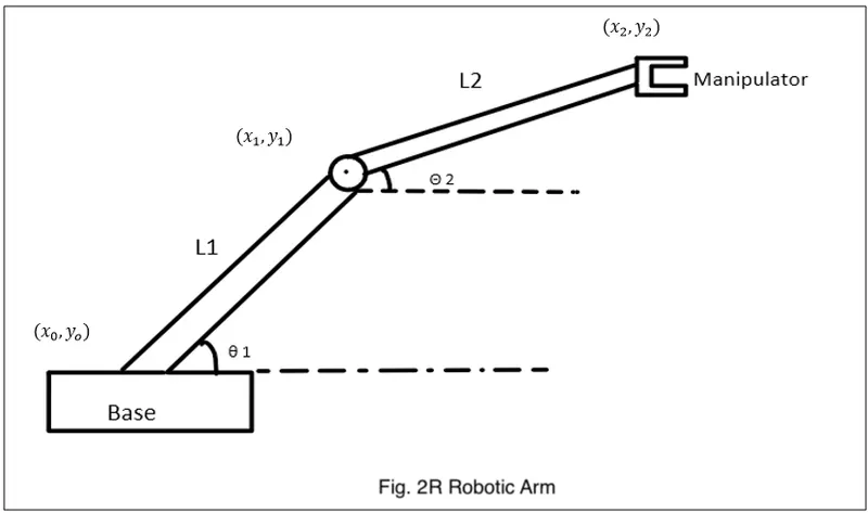
Given a kinematic chain composed of links and joints with multiple degree of freedom, finding the position and orientation of the end-effector in the operational workspace when all the joint parameters are known. This is called Forward Kinematics.
- Kinematic chains: Kinematic chain is the assembly of links connected by joints to produce a desired motion. Human arm is an example of a kinematic chain
- Links: Links are rigid bodies that gives structure to the robot.
- Joints: Joints are the movable parts(actuators) of the robots that connects the links of the robot. Joints cause relative motion between adjacent links.
- Degree of Freedom (DOF): Degree of freedom in robotic is simply the total number of independent joints which can change the pose of the robot.
- End-Effector: End-effector is the last link of the robot arm or manipulator that interacts with the environment. The last link can be gripper tool to do pick and place actions or a welding gun or simply a magnet.
- Workspace: Workspace is the space in which your robot can work i.e., all reachable points by the robot's end effector constitutes to workspace.
In this case there are 2 Links and 2 Rotational Joints. If theta1 and theta2 are given (fig. 2R Robotic Arm) then determining the final position of the end effector or manipulator is called Forward Kinematics.
So first to calculate the position of Link1 of length(L1) there are two end points which are as starting point (x0, y0) and ending point (x1, y1). Starting point is fixed to the base of the Robot so the coordinates are going to be (0, 0). End point is connected to the Link2 so it is also the starting point of the Link2 and the coordinates are (L1*cosd(theta1), L1*sind(theta1)). At last the end point of the Link2 of length(L2) whose coordinates are (x2, y2) which is (x1 + L2*cosd(theta1), y1 + L2*sind(theta2)).
3 coordinates has been determined [(x0, y0), (x1, y1), (x2, y2)].
Where,
Length of Link1(L1) = 1 m
Length of Link2(L2) = 0.5 m
Coordinates,
x0 = 0
y0 = 0
x1 = L1*cosd(theta1)
y1 = L1*sind(theta1)
x2 = x1 + L2*cosd(theta1)
y2 = y1 + L2*sind(theta2)
Instead of cos/sin cosd/sind is mention and the reason is in Matlab cos/sin function expects inputs in Radians where as cosd/sind expects inputs in Degrees and the values for theta are in degrees.
Program:-
To simulate the forward kinematics of a 2R Robotic Arm two programs has been executed as Initial and Final Program. Where in the Initial Program theta values are being changed manually to change the plot and in Final Program theta values are multiple and are changed the plot through programming.
Dividing a program into two makes easy to understand the concept of Forward Kinematics of a 2R Robotic Arm. At the end initial program is merged into the final program and with some additional steps program has been executed for the required output.
Initial Program:-
% Forward_Kinematics_of_a_2R_Robotic_Arm(Initial_Program)

clear all
close all
clc

% Inputs
L1 = 1;
L2 = 0.5;

theta1 = 45;
theta2 = 90;

% Coordinates
x0 = 0;
y0 = 0;

x1 = L1*cosd(theta1);
y1 = L1*sind(theta1);

x2 = x1+L2*cosd(theta2);
y2 = y1+L2*sind(theta2);

% Plotting
line([x0 x1], [y0 y1], 'linewidth', 3, 'color', 'b')
line([x1 x2], [y1 y2], 'linewidth', 3, 'color', 'r')- In the initial Program, length of the links(L1 & L2 ) are going to be fixed as shown above where as theta values are taken as theta1 = 45° and theta2 = 90°. To change the plot theta values are being changed manually.
- In this program a plot is created with two lines to visualise the Robotic Arm using “line” command with 3 coordinates [(x0, y0), (x1, y1), (x2, y2)] which joints the two lines or arms and created a plot.
- Also “linewidth” parameter is given as 3 to get a bit thicker line with color red and blue. Finally a simple Forward Kinematics simulator is created.
Final Program:-
- Here the objective is to have multiple values of theta1 and theta2 and for each value of theta and theta2 plot is created and at the end a movie is made of the plot.
% Forward_Kinematics_of_a_2R_Robotic_Arm(Final_Program)

clear all
close all
clc

% Inputs
L1 = 1;
L2 = 0.5;

theta1 = linspace(0, 90, 10);
theta2 = linspace(0, 90, 10);

% for_end_loop
ct = 1;

for i = 1:length(theta1)
    THETA1 = theta1(i);

for j = 1: length(theta2)
   THETA2 = theta2(j);

% Coordinates
x0 = 0;
y0 = 0;

x1 = L1*cosd(THETA1);
y1 = L1*sind(THETA1);

x2 = x1+L2*cosd(THETA2);
y2 = y1+L2*sind(THETA2);

% Plotting
plot([x0 x1], [y0 y1], [x1 x2], [y1 y2], 'linewidth', 3)
axis([-0.1 2 0 2])
pause(0.1)
M(ct) = getframe(gcf);
ct = ct+1;
end
end

% Creating_animation_of_the_plot
movie(M)
videofile = VideoWriter('Forward_Kinematics_of_a_2R_Robotic_Arm.avi','Uncompressed AVI');
open(videofile)
writeVideo(videofile, M)
close(videofile)- Length of the links(L1 & L2) are fixed as shown above but the theta values are going to be array with “linespace” command from (0° - 90°) with 10 values in between them for each theta. theta1 and theta2 are having 10 values between 0° to 90°.
- For each value of theta1 and theta2 initial program is going to get repeated. Also the values are going to get change through programming instead of changing it manually. Hence “for loop” concept is used.
- For theta1 loop counter is (i) which determine how many times the “for loop” is going to get executed and I.e, 1 to length(theta1) which will be 10 values from 0° to 90° as length(theta1) refers to the number of values for theta1.
- Value of (i) is going to change for every iteration and it is going to store only one value at a time as it is not an array. Each time the value changes it’s going to execute the command present inside the for loop.
- Command present inside the for loop is THETA1 which is a variable and that is going to represent an array theta1(i). Which means for every value of theta1 THETA1 is going to get executed for (i) times.
- For each value or position of THETA1 or Link1 Link2 takes multiple positions depends on theta2 hence another “for loop” is assigned for loop counter (j) and variable THETA2 is goint to represent theta2(j) times.
- So for the coordinates theta1 is equals to THETA1 and theta2 is equals to THETA2.
- “plot” command is used here instead of “line” as an animation is needed to create including all the coordinates which is going to be a plot of 100 values.
- Axis has been selected as (-0.1 to 2, 0 to 2). Also pause of (0.1) is given for the plot to demonstrate all values of the Links.
- A counter(ct) is added which consists of all frames that are executed and it’s value is 1 I.e from the starting and for every iteration it’ll be incrimented with addition of 1 so automatically next frame will be excuted.
- Now (ct) is assigned with an array M and also saves the current figure window with command “getframe(gcf)”. This is to create a movie with M.
- At the end of the “for loop” “movie(M)” is used to create a movie of M. Then an avi file is created as ‘videofile’ using “videowriter” command with filename ‘Forward_KInematics_of_a_2R_Robotic_Arm.avi’ and profile ‘Uncompressed AVI’.
- Now to open the videofile ‘open(videofile)’ is used then to write the videofile ‘writevideo(videofile, M)’ is used. Then to close the videofile close(videofile) is used.
Results:-
A program is created in Matlab to simulate the forward kinematics of a 2R Robotic Arm, also an animation file of the plot is created.
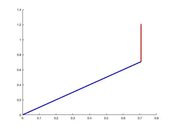
In the Initial Program fixed Robotic Arms can be seen as theta values are needed to change manually so at a time only one angle of theta1 and theta2 can be seen.
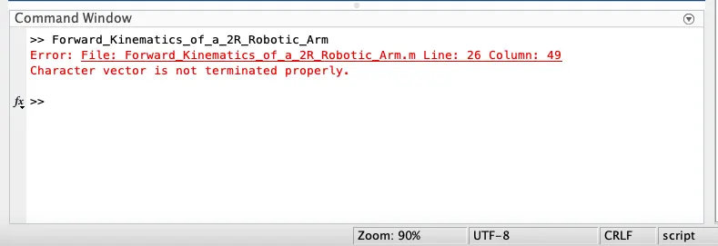
Above error was occurred and to resolve it, semicolon was removed from color ‘r’.
Animaton:-
In Final Program through the simulation we can see that for each value of THETA1 THETA2 changes and repeat itself. Also workspace of the end effector or manipulator can be imagine.
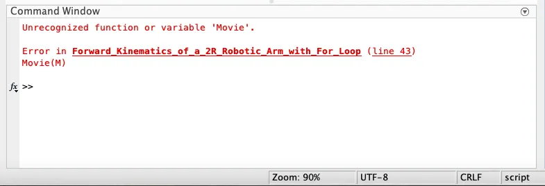
Above error was occurred and by writing Movie in lower case I.e. movie it has been resolved.