Wiring harness design in CATIA V5 - 3D modeling Week 5 & 6 Challenge
- Harness A :
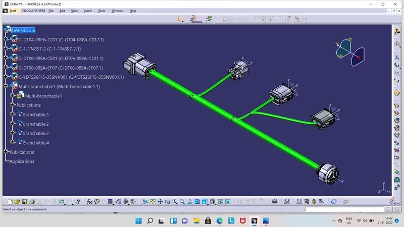
- For routing the above shown in image Harness A, we have to first define, all Connectors as Electrical Part in Electrical Part Workbench.
- We have to make Points and Axis for each Connector individually in Part Workbench.
- Then move to Electrical Part Work Bench, here by using tools 'Define Connector', 'Define Connector Connection Point', 'Define Bundle Connection Point', with respective Points and Axis, Connector will get define electrically.
- As all Connector defined electricaly, then save that file and create Catalog file for those Connectors.
- Then switch to Electrical Harness Assembly Workbench, here we have to first click on 'Geometrical Bundle' tool and then on name of product in the tree structure. So icon will get changed there and Publication also displyed.
- After that, import all the required Connectors from Catalog one by one, by click on book like icon and choose the Connectors Catalog file and from there select required Connectors.
- Give position to all Connectors as per ask in question. Once all Connectors placed to their respective positions, then we can move for routing the wire from them.
- So, to route the bundle, click on 'Multi- Branchable Document' tool, so Electrical Harness Installation Workbench will get open.
- Here we have to give diameter for wire and and value for Bend Radius Ratio, which is generally 1.4. Then click on Route Definition option, select the Connectors between which bundle we need.
- Now we have give branch point at respective places. So click on 'Add Branch Point' tool and select the bunddle, give the point at respective position. Hence, Bundle get split in segment. Similarly, give Branch points at places where we desire a branch from there.
- In this way routing between all Connectors can be done. So we can get Connectivity as shown in above image.
- If there is any error in routing, then in the Tree Structure Yellow Colour with Flash icon will display at respective branch.
- But here, in this Harness A there have not any error, so its not showing any update error.
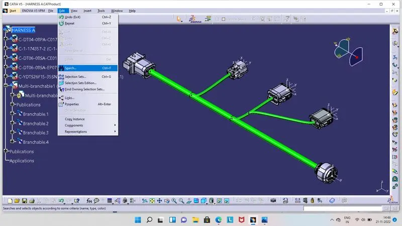
- Once routing will be done, then we have to check that Bundle Segments are Fully Connected or not.
- For that, click on Edit option, then on Search option, as shown in above image.
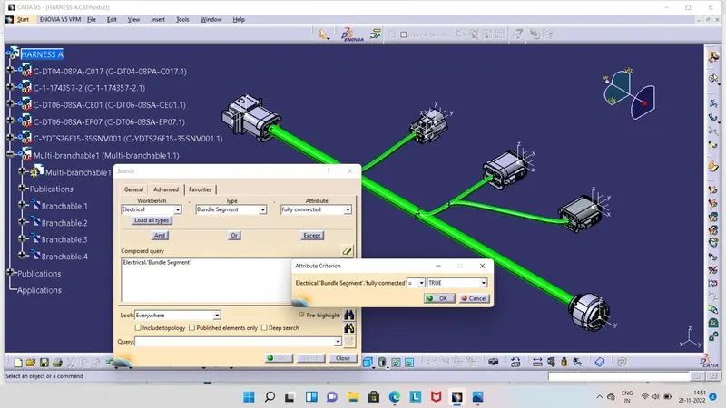
- As we click on Search option, one box will get appear on screen as shown in above image.
- Here, we have to click on Advanced option, in Worbench section we have select Electrical.
- Type is Bundle Segment and Attribute is Fully Connected.
- As we select Fully Connected option, one another box will get appear on screen, in which we have to select, TRUE Or FALSE option.
- True is for which Bundle Segments are connected and False is for which are not connected.
- So here we have click on True option.
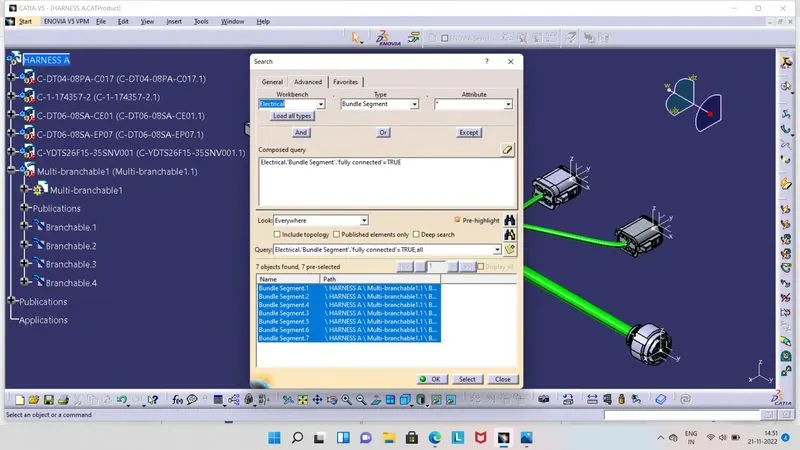
- After click on True option, we have to click on search icon. So there will be display information of connected Bundle Segment.
- As shown in above image, there is information displayed of conneted Bundle Segments. So here all Bundle Segments are connected.
- In this way we can check for connectivity of Bundle Segments.
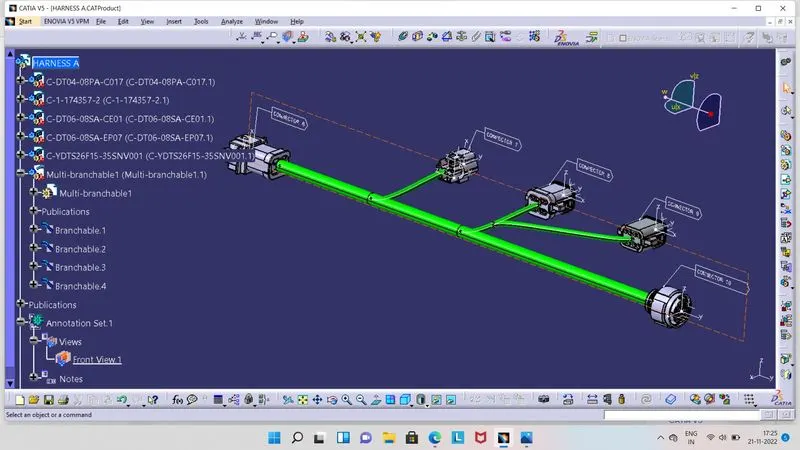
- In above image we can see that, we have given name indicator to each Connector, it is a 3D Anotation.
- It is used for ease to indentify Connectors, wherever large number of Connectors are invove in a sigle circuit.
- To give 3D Anotation, we have to switch into Mechanical Assembly Workbench and ensure that Geometrical Bundle we have created before switching.
- Then in Assembly Workbench, click on 'Front View/ Anotation Plane' tool and select any plane from Connector for its indication by typing name.
- Then click on 'Flag Note with Leader' tool and click on Connector at any point, from where we desire to show its name. So one box will get appea, there we have type name as per need for respective Connector.
- Similarly, for remaining Connectors we have to give name, So eventualiy we can see the result as shown in above image, Connector 6, 7, 8, 9, 10.
- Also in tree structure, there is a Anotation Set involved.
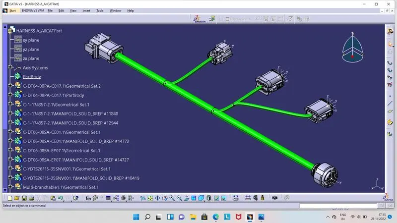
- Now we have to convert Electrical Product file into CatPart file as shown in above image.
- For that, click on Tools option and select the ' Generate CATPart from Product' option. So ne box will pop up there, now click on Harness A in tree structure.
- So, Product file will get converted into the CatPart file.
- CatPart file is generally easy to run in software, while Product file get hangs, after closing and opening the save data.
- Harness B :
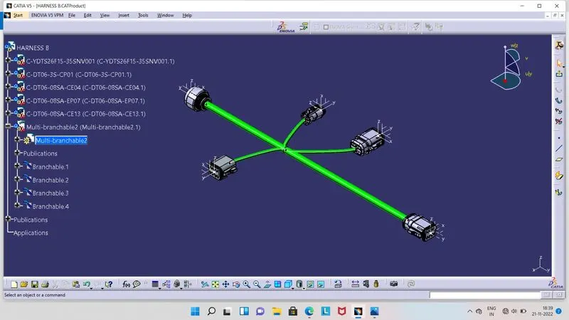
- For routing the above shown in image Harness B, we have to first define, all Connectors as Electrical Part in Electrical Part Workbench.
- We have to make Points and Axis for each Connector individually in Part Workbench.
- Then move to Electrical Part Work Bench, here by using tools 'Define Connector', 'Define Connector Connection Point', 'Define Bundle Connection Point', with respective Points and Axis, Connector will get define electrically.
- As all Connector defined electricaly, then save that file and create Catalog file for those Connectors.
- Then switch to Electrical Harness Assembly Workbench, here we have to first click on 'Geometrical Bundle' tool and then on name of product in the tree structure. So icon will get changed there and Publication also displyed.
- After that, import all the required Connectors from Catalog one by one, by click on book like icon and choose the Connectors Catalog file and from there select required Connectors.
- Give position to all Connectors as per ask in question. Once all Connectors placed to their respective positions, then we can move for routing the wire from them.
- So, to route the bundle, click on 'Multi- Branchable Document' tool, so Electrical Harness Installation Workbench will get open.
- Here we have to give diameter for wire and and value for Bend Radius Ratio, which is generally 1.4. Then click on Route Definition option, select the Connectors between which bundle we need.
- Now we have give branch point at respective places. So click on 'Add Branch Point' tool and select the bunddle, give the point at respective position. Hence, Bundle get split in segment. Similarly, give Branch points at places where we desire a branch from there.
- In this way routing between all Connectors can be done. So we can get Connectivity as shown in above image.
- If there is any error in routing, then in the Tree Structure Yellow Colour with Flash icon will display at respective branch.
- But here, in this Harness A there have not any error, so its not showing any update error.
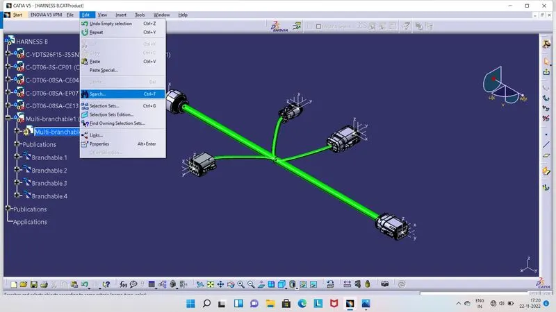
- Once routing will be done, then we have to check that Bundle Segments are Fully Connected or not.
- For that, click on Edit option, then on Search option, as shown in above image.
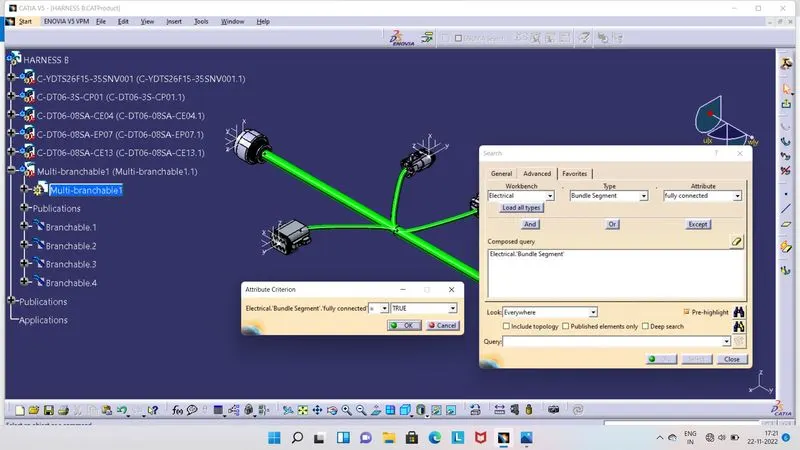
- As we click on Search option, one box will get appear on screen as shown in above image.
- Here, we have to click on Advanced option, in Worbench section we have select Electrical.
- Type is Bundle Segment and Attribute is Fully Connected.
- As we select Fully Connected option, one another box will get appear on screen, in which we have to select, TRUE Or FALSE option.
- True is for which Bundle Segments are connected and False is for which are not connected.
- So here we have click on True option.
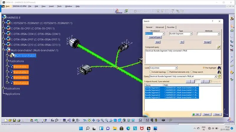
- After click on True option, we have to click on search icon. So there will be display information of connected Bundle Segment.
- As shown in above image, there is information displayed of conneted Bundle Segments. So here all Bundle Segments are connected.
- In this way we can check for connectivity of Bundle Segments.
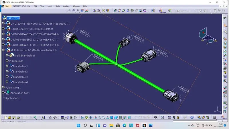
- In above image we can see that, we have given name indicator to each Connector, it is a 3D Anotation.
- It is used for ease to indentify Connectors, wherever large number of Connectors are invove in a sigle circuit.
- To give 3D Anotation, we have to switch into Mechanical Assembly Workbench and ensure that Geometrical Bundle we have created before switching.
- Then in Assembly Workbench, click on 'Front View/ Anotation Plane' tool and select any plane from Connector for its indication by typing name.
- Then click on 'Flag Note with Leader' tool and click on Connector at any point, from where we desire to show its name. So one box will get appea, there we have type name as per need for respective Connector.
- Similarly, for remaining Connectors we have to give name, So eventualiy we can see the result as shown in above image, Connector 1, 2, 3, 4, 5.
- Also in tree structure, there is a Anotation Set involved.
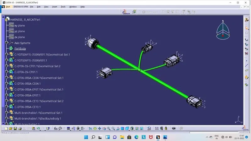
- Now we have to convert Electrical Product file into CatPart file as shown in above image.
- For that, click on Tools option and select the ' Generate CATPart from Product' option. So ne box will pop up there, now click on Harness A in tree structure.
- So, Product file will get converted into the CatPart file.
- CatPart file is generally easy to run in software, while Product file get hangs, after closing and opening the save data.