Wiring harness design in CATIA V5 - 3D modeling Week 5 & 6 Challenge
Report
step1: import the connector from the te.com and then all connector are defined in electrically.
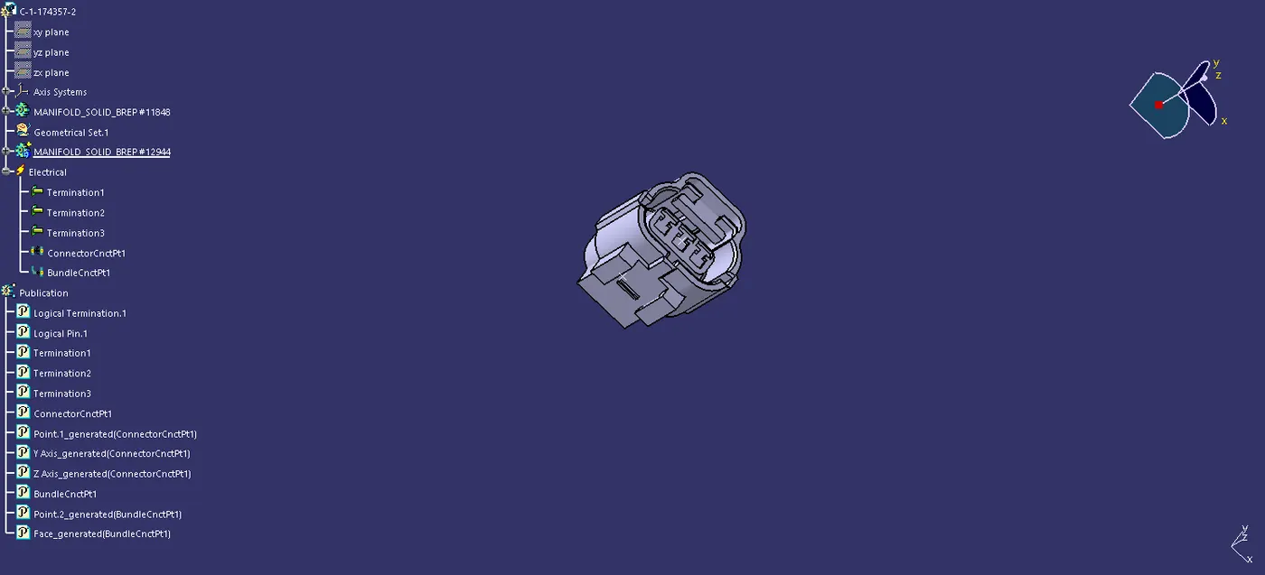
Step2: in the connector placed the point in the connector connecting side bundle connector side and the making the axis of the connector connecting side of the connector for the perpose of the coordinate the matting part.
Step3: Axis is created by the connector connecting side in Y axis is the coordinate direction of the connector and z axis is the coincident for the connectors.
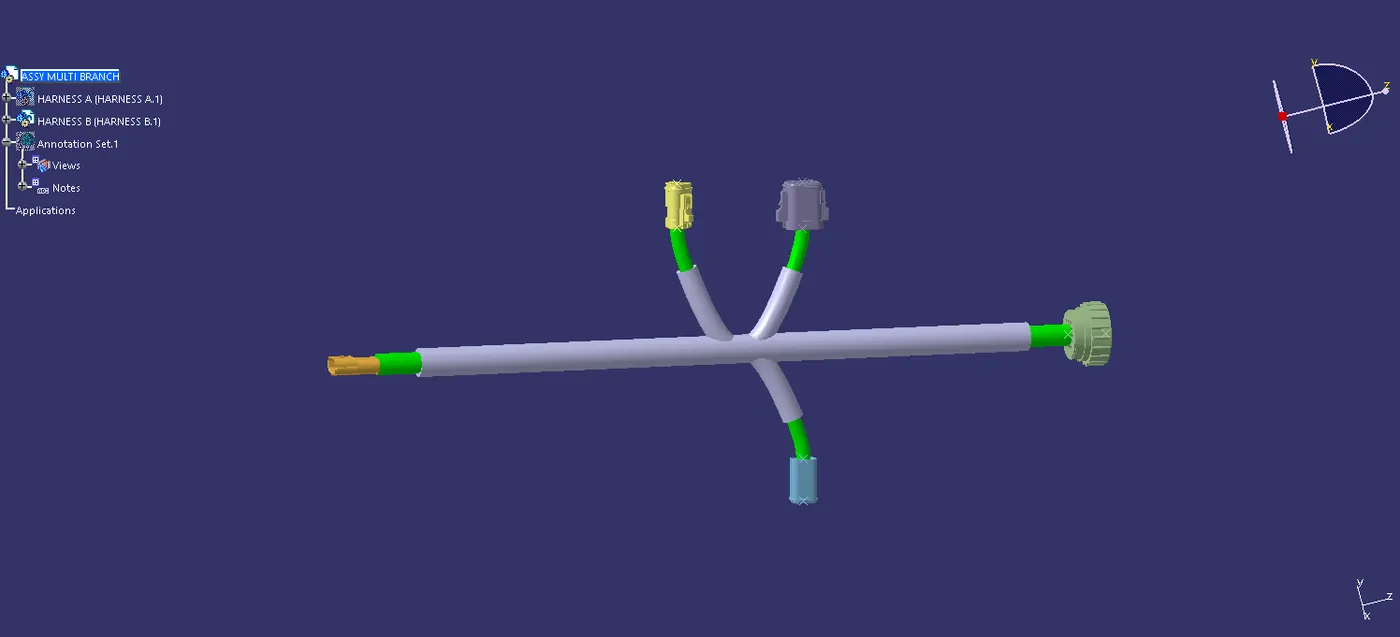
Step4: After tha creating the product file and make a separe geomertic file in the assembly workbench. and imported the all connector and the connectors are placed in the required place of the connector connection.
Step5: After that move into the harness installation workbench to routing the harness for the connectors and then using the catalogue of already used in the design for the standard that is used for making the protection cover for the harness
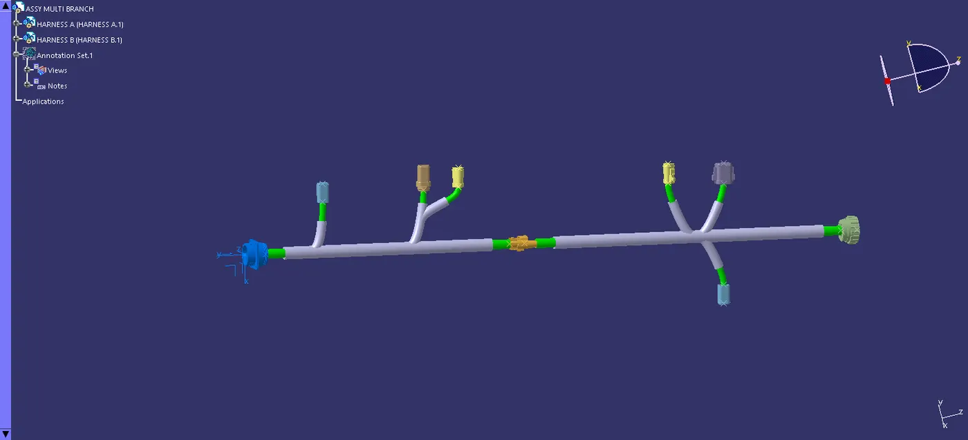
Step6: Then move into the assembly bench make a two harness is into one with using the snap or the smart move to and connect the connector.and then checking the connectivity of the harness in using the edit tool and search advance, then electrical,bundle segment, fully connected the give search and that show the flase connection in the harness.
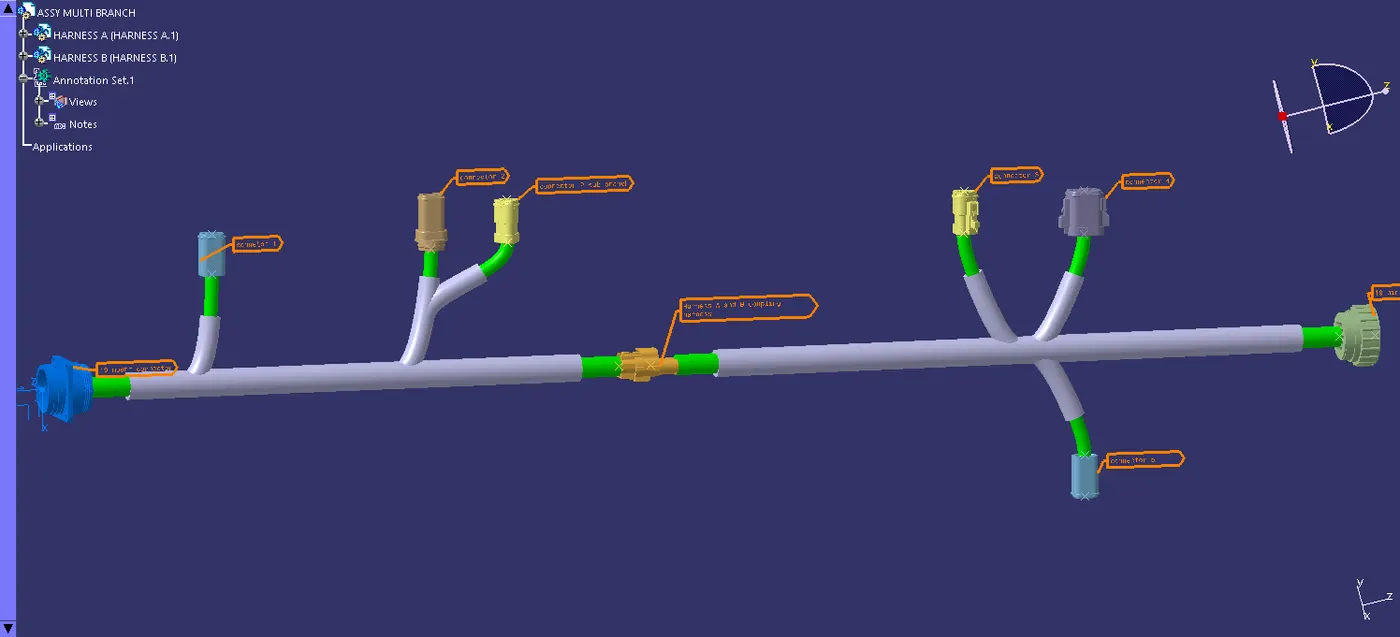
Step7: in annotation is used for the make a clear understanding for the maufacture.