Wiring harness design in CATIA V5 - 3D modeling Week 5 & 6 Challenge
Report on week 5 and week 6 challenges:
Aim and objective:
In this challenge, I have to
1. First complete Harness A and Harness B in the product file.
2. Then, I have to rout the bundles to the connectors.
3. Then add harness A and Harness B electrically.
Define all the connectors of both the harness A and B:
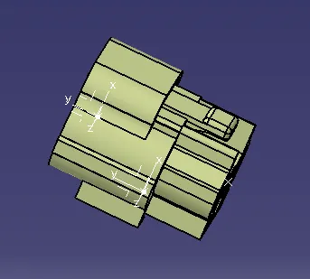
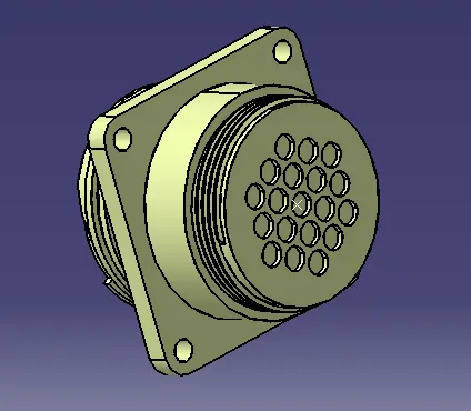
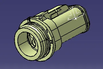
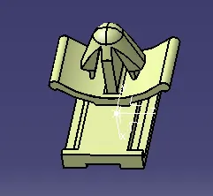
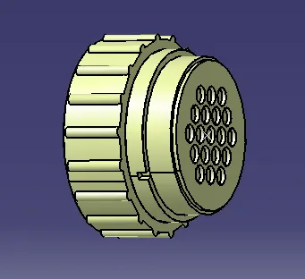
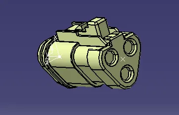
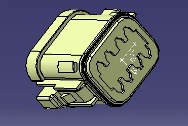
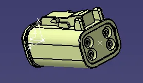
Open all the connectors in the CATIA V5. Then switch to part design workbench and create necessary geometries like point, planes or axis systems. Then switch to the electrical part design workbench and define the connector electrically. Define the bundle entry point as well as the connector connection point and also the cavity connection point for the mounting clip.
Image of the part:
Component of harness A:
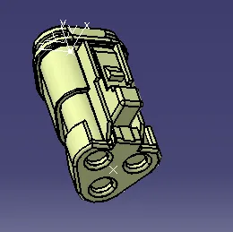
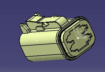
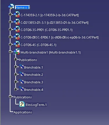
Components of harness B:

Routing in Harness A and B:
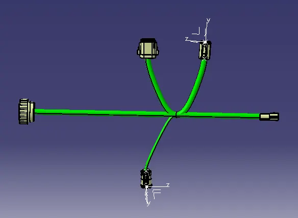
To rout the wires I have to define and place all the connectors at their desired location. To do that I have drawn lines based on one connector location. Then I used the snap command in the assembly workbench and placed all the connectors accordingly. Now, go to the electrical harness assembly workbench and define the product as a geometrical bundle. Then use the branchable command to rout the wires. Use the add branch point command to create a new branch point on the main branch. Then again use the branch definition command to add the connectors using sub-branches. This same process is followed in the routing of Harness A and Harness B.
Image of the harness A:
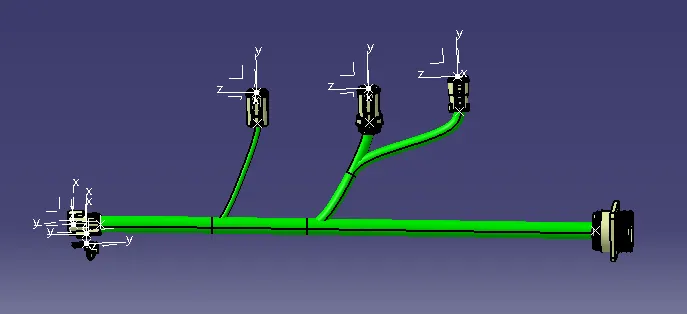
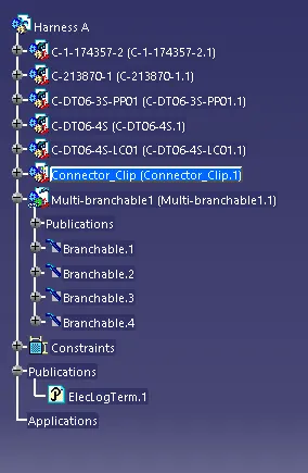
Image of the harness B:
Connecting the two harnesses:
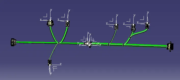
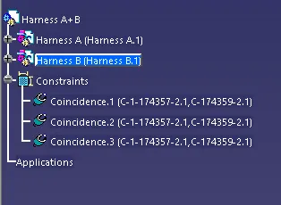
In harness A, the female part of the mating connector and mounting clip is present and in harness B, the male part of the mating part is present. Now, copy both the harnesses into one product file. Then go to the electrical assembly workbench and connect the mounting clip and the connectors. In that way, the two connectors are connected electrically.
Finding whether the bundles are fully connected or not:
For that, we have to use the search command. In the search command, we have to select the workbench as electrical, in the type we have to select bundle segment and in an attribute we have to select fully connected and make it false. The result will show the wire which is not connected.
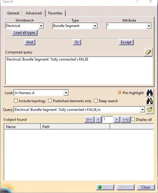
Annotation:
First, we have to switch to the mechanical assembly workbench. Here we have to create the view on which we will give annotation. Then select flag with note or note only to give the annotation to the component of the harness assembly.
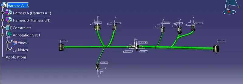
Conclusion:
All the connectors are defined separately and routed properly. Both the harness assembly are then interconnected. And finally, checking the bundle segment continuity and also the annotation part is done. All these works are done using different workbenches in the Catia V5 environment.