Wiring harness design in CATIA V5 - 3D modeling Week 5 & 6 Challenge
Q1.
Step 1: Download all the respective connectors and save the part files in respective folders.
Step 2: In Part Design, Create points and Axis system to the Connectors as shown below
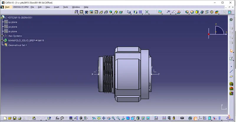
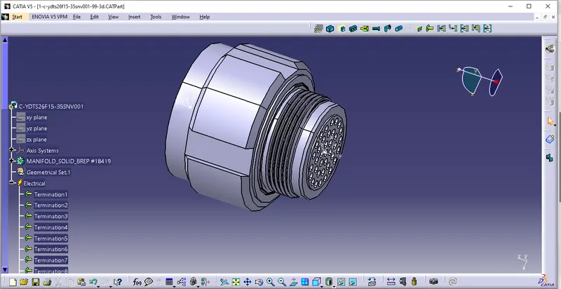
Step 3: In Electrical Part Design, Define the Connector and Define Bundle connection point as shown below
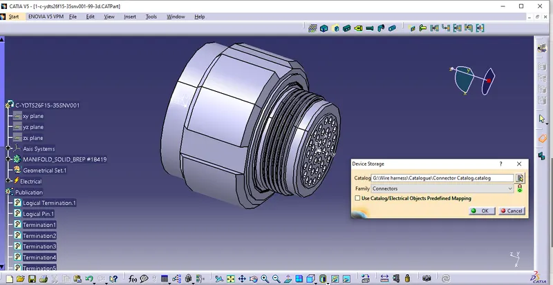
Step 4: Store the Connector in the respective catalogue for Future use as shown below
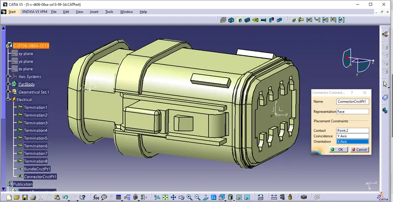
Step 5: Repeat Step 2, 3 & 4 for all the remaining connectors. Define Connector Connection point for Connector 5 as shown below.
Step 6:Place all the connectors in a new product "Harness B" as shown below
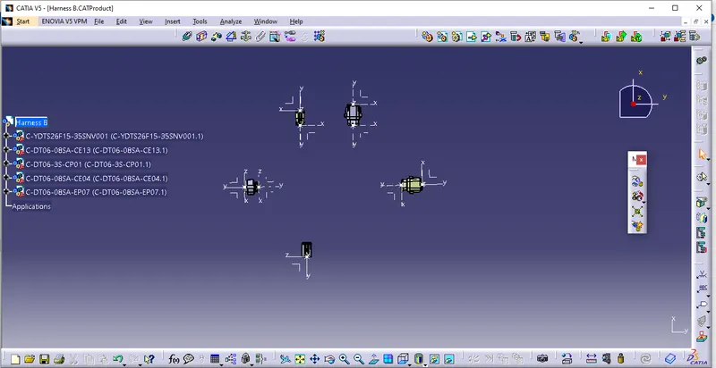
Step 7: In Electrical harness assembly , use Geometrical Bundle option to electrify the product as shown below
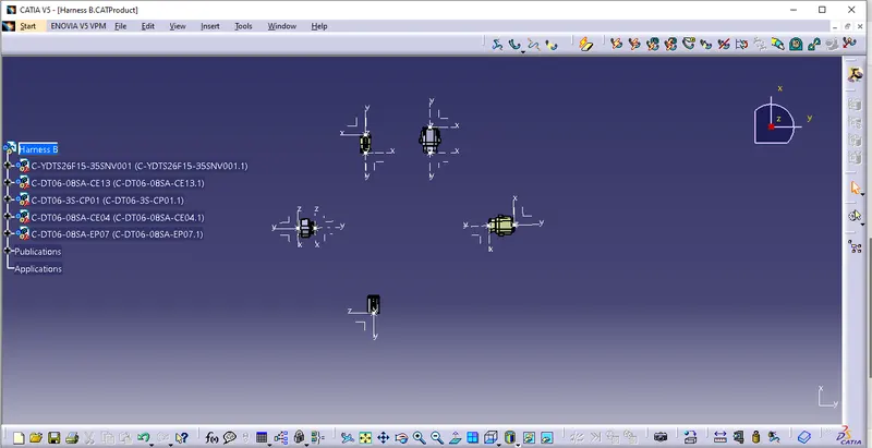
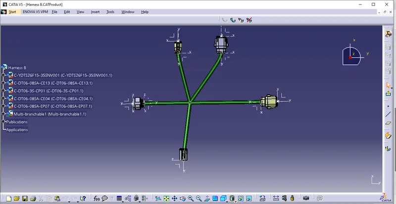
Step 8:Start Routing the Bundle and add branch point at desired length and complete the routing as shown below
Step 9: Follow the same steps from 1 to step 8 to create Hareness A as shown below
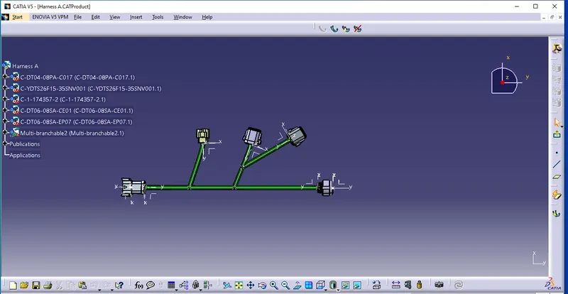
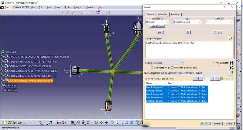
Step 10: Check the Bundle connectivity in selecting the Multibranchable, then in edit go to search, in advanced, select electrical, bundle segment and fully connected as shown below
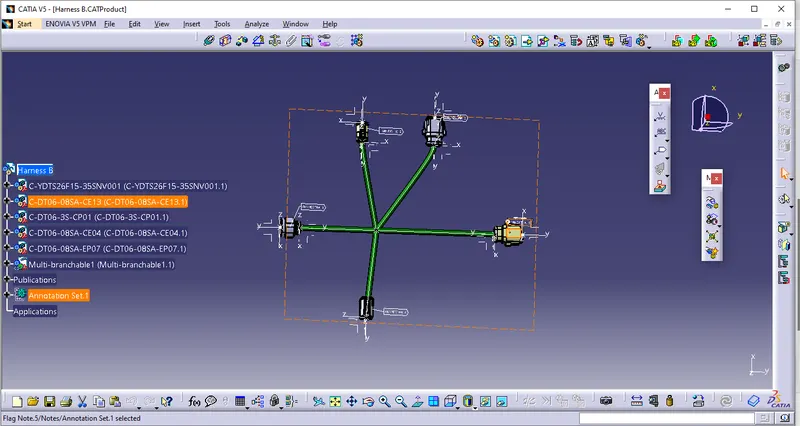
Step 11: Add annotation to all the connectors in Assembly design as shown below
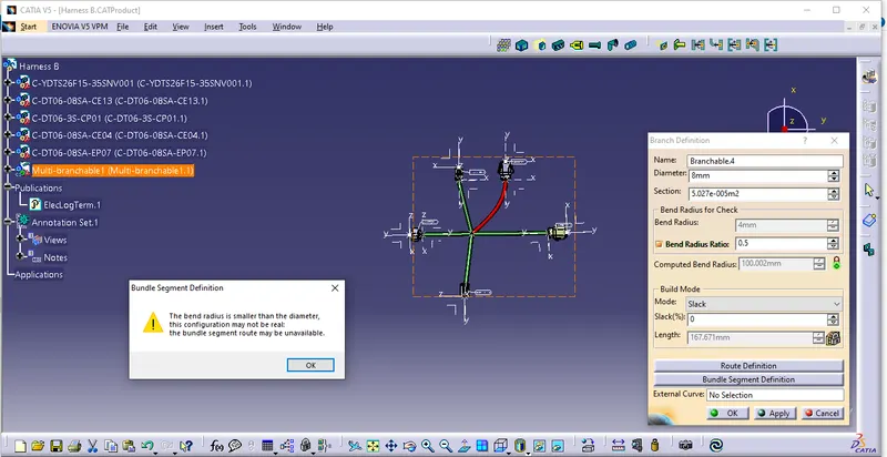
Step 12: Bundle warning is shown below for bend radius is smaller than the diameter
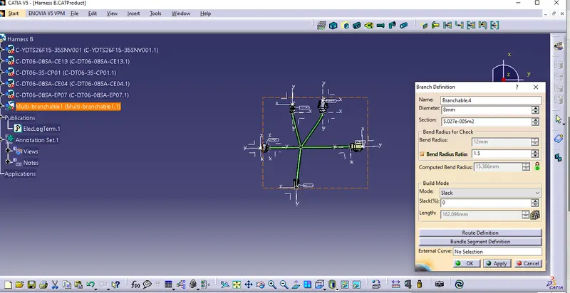
Hence ratio shall be miniumum 1.5 to resolve it
Step 13: In mechanical assembly work bench, use tool option and use "Generate CAT part from product" for the product as shown below
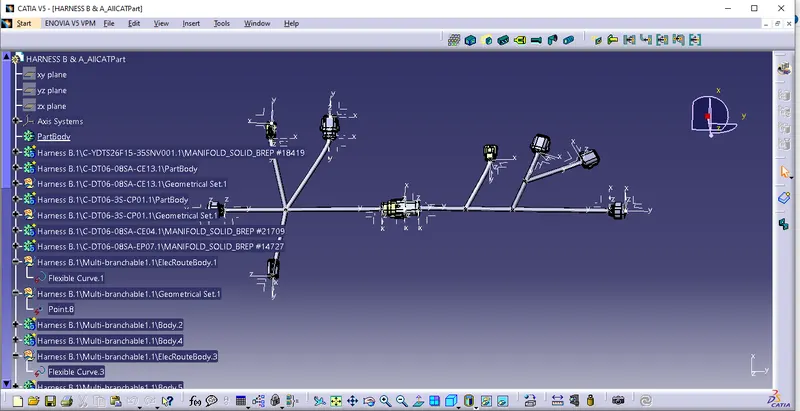
please find all files attached or reference.