Wiring harness design in CATIA V5 - 3D modeling Week 4 Challenge
Step 1:
Downloading all the connector 3D models from www.te.com and saving it in the respective folders.
Step 2:
Open part design and construct point and axis system for the connectors as shown below.
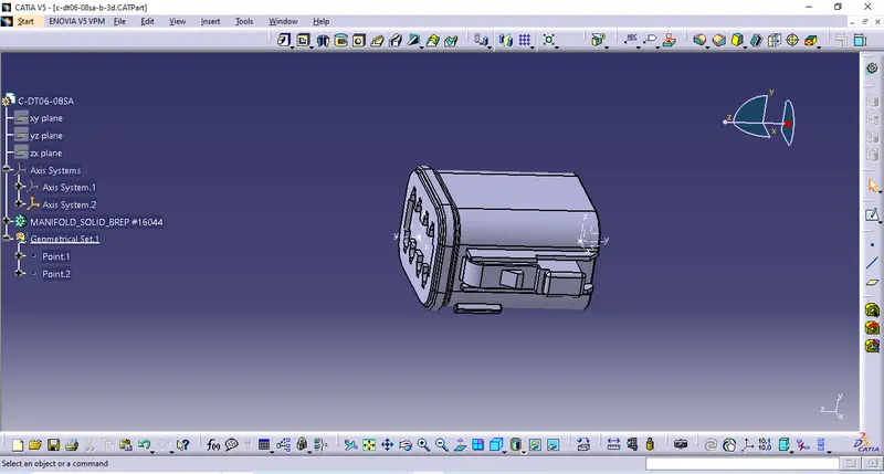
Step 3:
Switch to Electrical part deisgn and define connector as Electrical using "define connector " option
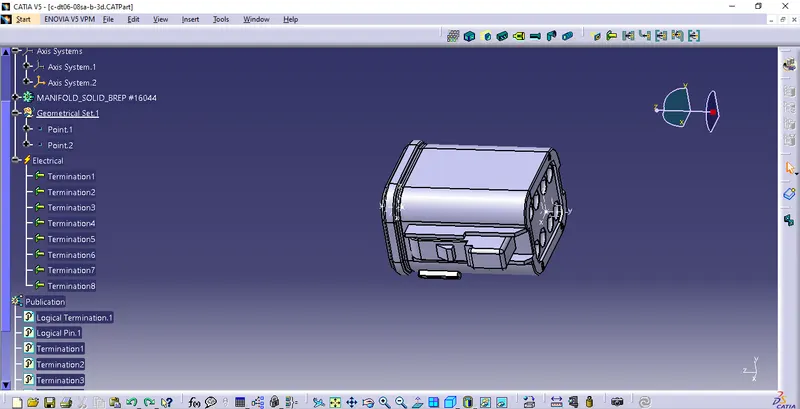
Step 4:
Use "Bundle connection point" option as shown below
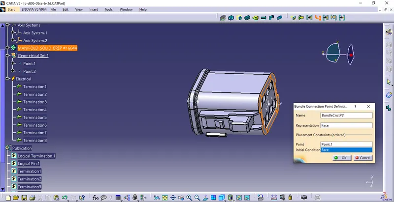
Step 6:
Define Connector Connection point for the conector as shown below
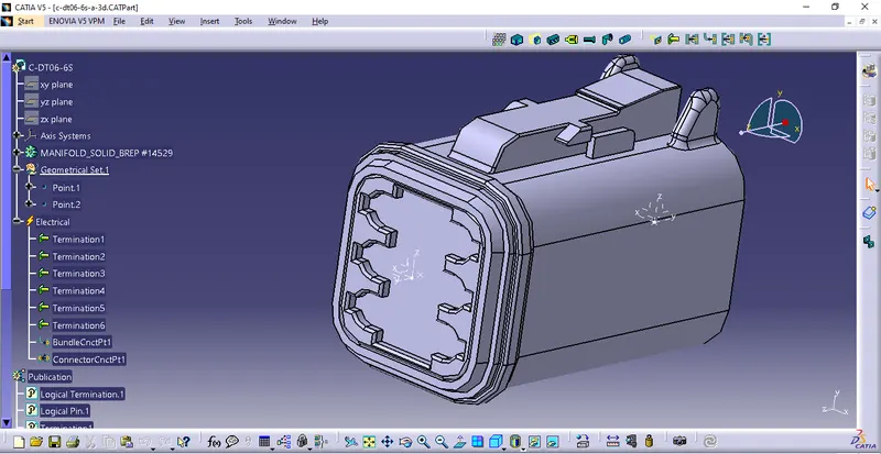
Step 6:
Save the Connector to the respective Catalogue for future use as shown below.
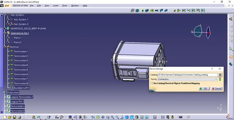
Step 7:
Repeat Step 2, 3 , 4, 5 & 6 for all the remaining connectors
Step 8 :
Open new Product file and Copy all the connectors as shown below
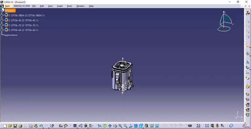
Step 9:
Place all the connectors accordingly using Compass or snap Features.
Step 10:
In Electrical harness assembly use "Geometric Bundle" option,to electrify the product.
Step 11:
In Electrical Hareness Installation, Route the connectors using "Multi branchable document", Add branch point as desired.
Step 12:
In Electrical harness assembly use "Protective Covering " option,to protect the routings as shown below.
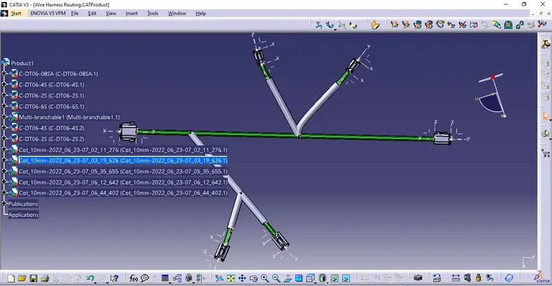
Step 13:
Use "save Management " option to save all the parts.