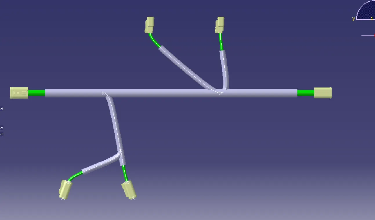
Wiring harness design in CATIA V5 - 3D modeling Week 4 Challenge
Electrical wiring harness of the target circuit needs many inputs such as electrical requirements, cad data for the devices, environment settings, insulation requirements etc. but we are setting up a small study circuit to learn the tools of the CATIA V5 Electrical Harness design.
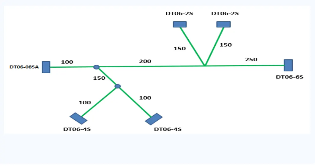
Our study circuit consists of 4 different connectors connected to each other as specified in the diagram.
The cad data of the given specific electrical connectors can be obtained from Tyco Electronics’ website. Initially all the electrical cad files are loaded into CATIA and proper geometric references are created and electrically define the “Connection Entry Point” and “Bundle Entry Point.”
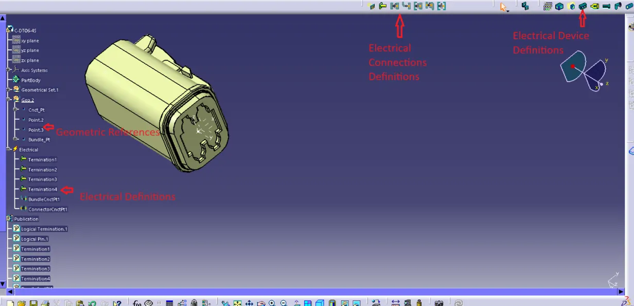
The electrical cad components created are stored in a suitable catalog file for ease of access. The family of this catalog is termed as connectors and named “DT-06” as this catalog consists of DT-06 series connectors.

The wiring harness design actually takes place in Assembly Workbench (both mechanical & electrical) where the electrical components are loaded and oriented properly in the workspace.
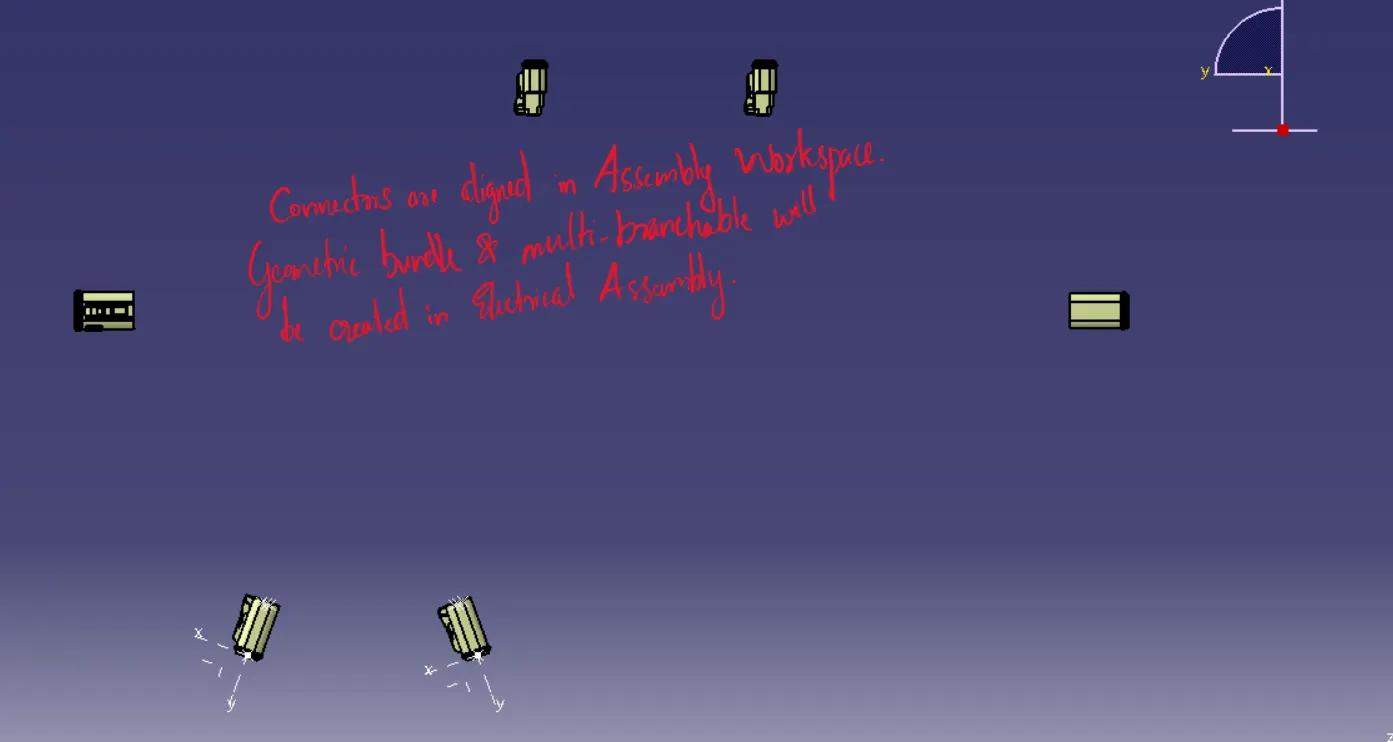
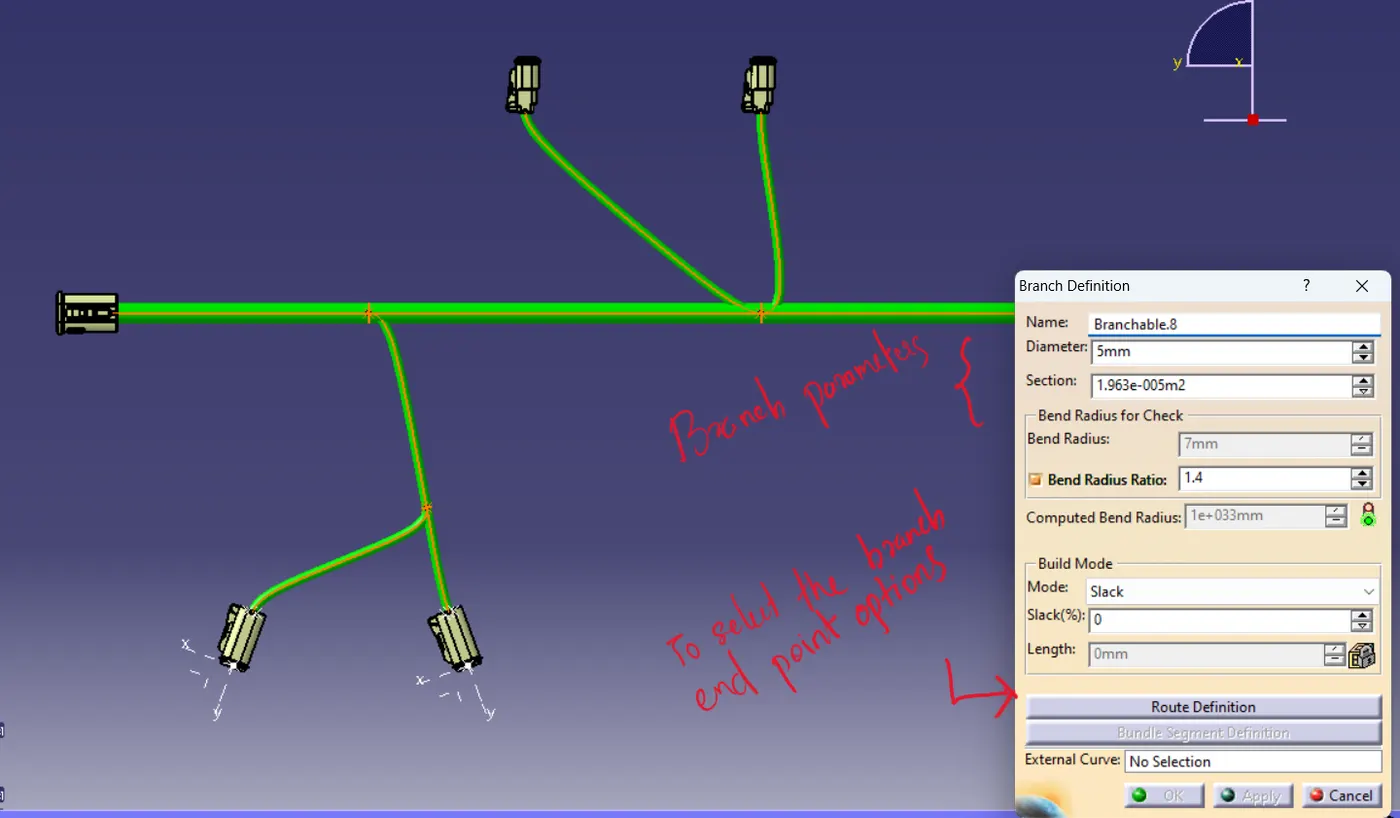
The workspace is converted to electrical harness assembly where the product file is defined as “Geometric Bundle” and a “Multi-branchable” is added between the extreme end connectors. Under “Route Definition” we get to choose the connectors and tangency of the bundle.
After the branchable definitions, we need to add “protective covering” which acts as insulation for the wiring under the same workspace. For this study, we are using “Corrugated Tubes” which were made earlier. The protective covering has the end extremities of 30 mm.
Rotating the electrical component in the harness file product can be done using the compass or manipulation tool. In my example, the electrical product is rotated along x-axis using compass tool.
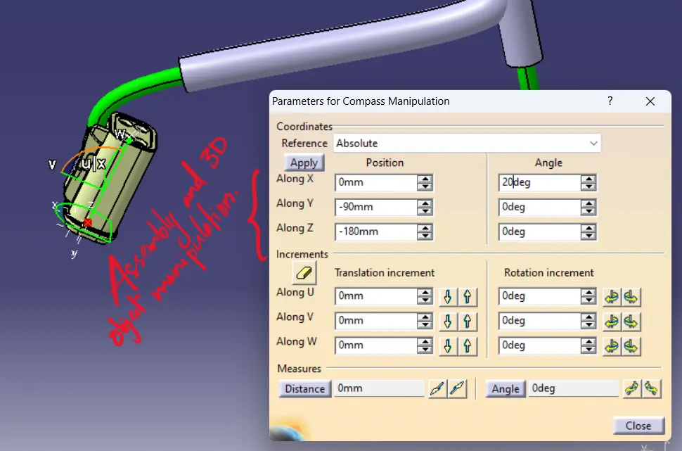
If the electrical components are modified in the assembly after the multi-branchable definitions are made, the harness is going to need updation.
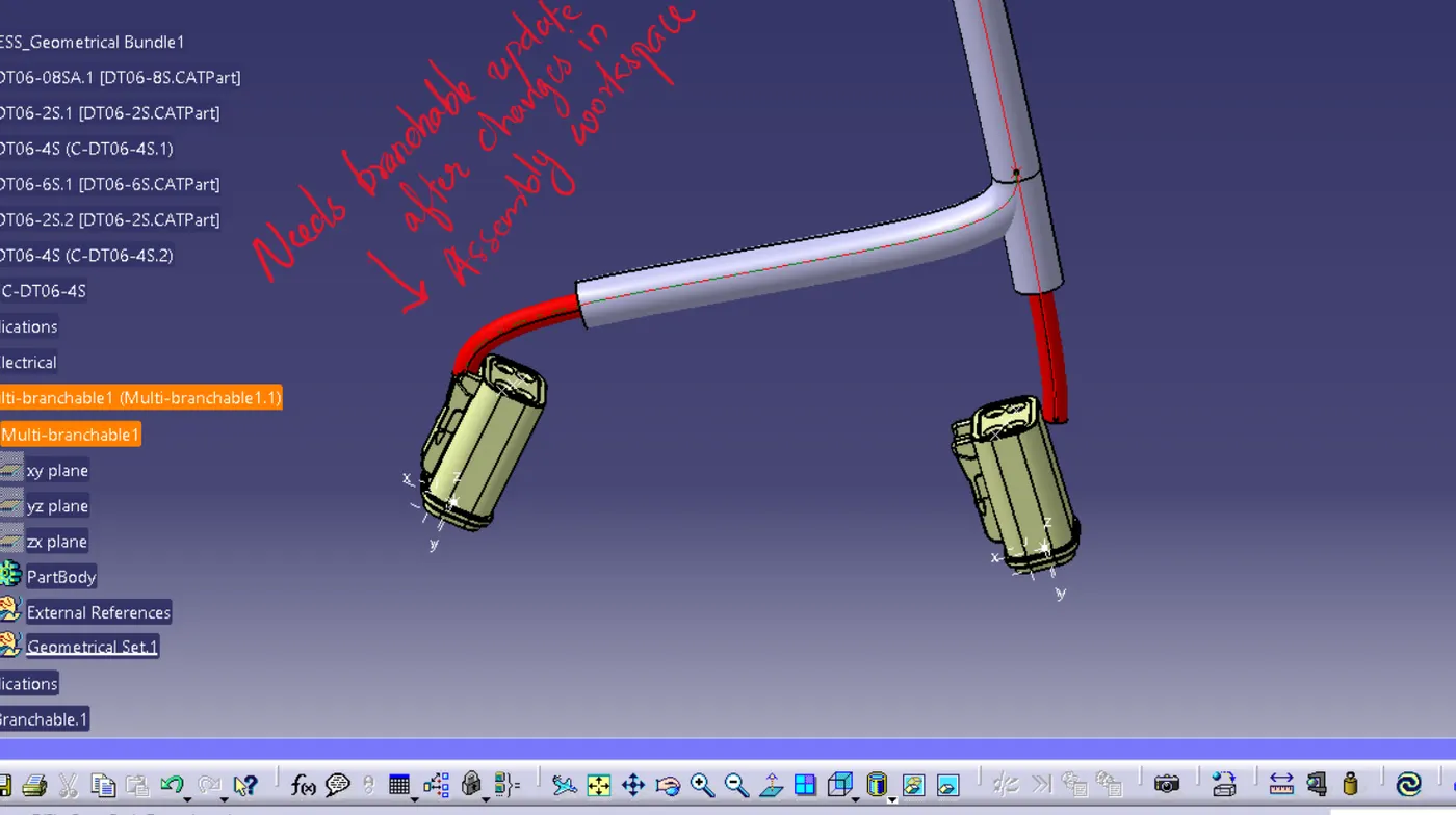
After updating the branchable, the cot tube which were added as protective covering is mis-aligned with the harness.
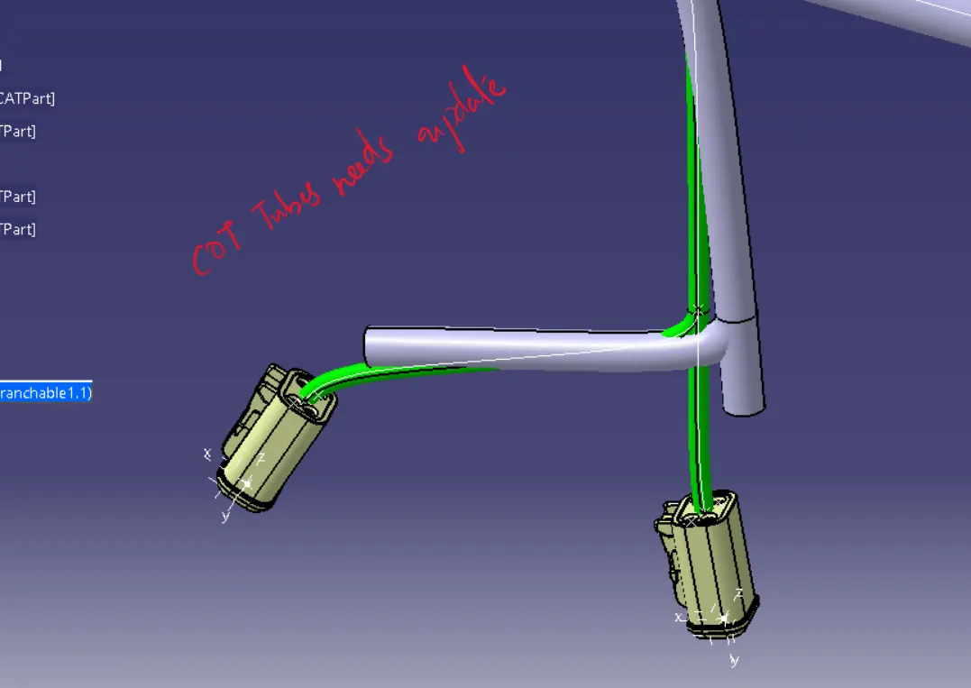
The mis-aligned protective covering, in this case COT_Tubes can be arranged properly by selecting them once again and clicking the “protective covering” tool under “Electrical harness assembly” design workbench.
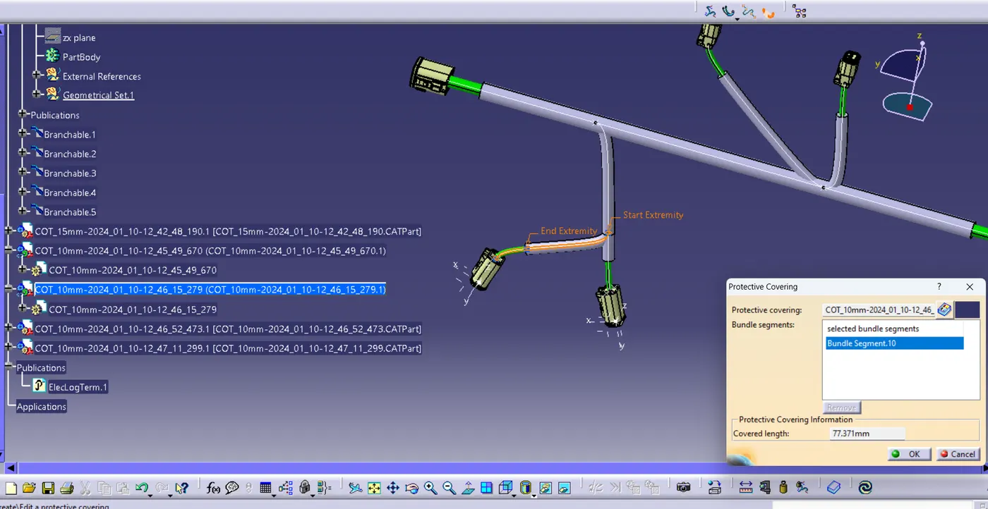
The final output of the electrical harness of the study circuit looks like below;