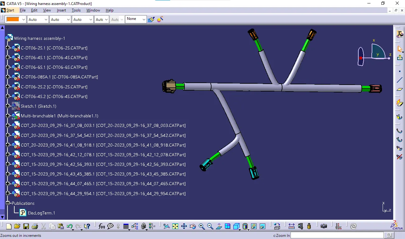
Wiring harness design in CATIA V5 - 3D modeling Week 4 Challenge
Route the following harness layout in Electrical workbench. Make assumption for harness bundle diameters. Use Following connectors as shown in layout diagram.
Add protective covering on all branches connected to DT06-2S & DT06-4S connectors. Keep end extremity at 30mm (from connectors end)
Download connector 3D data from www.te.com
- DT06-4S
- DT06-6S
- DT06-2S
- DT06-08SA
Answer:
1.DT06-2S
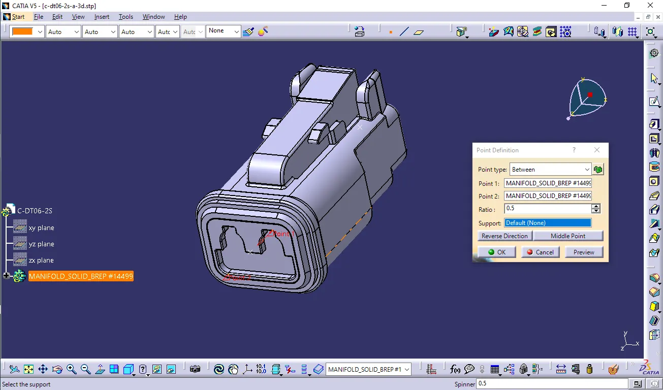
- Create midpoint on the contact face which will be normal to wire bunddle insertion.
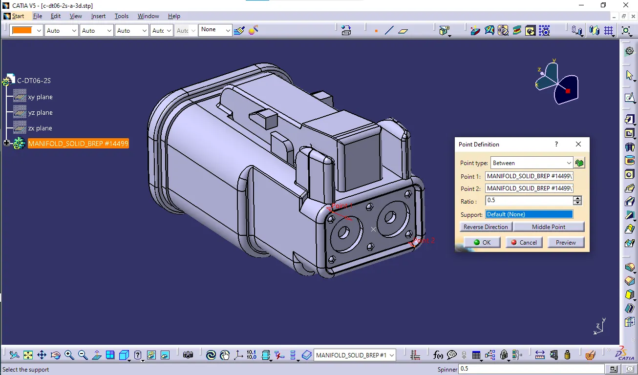
- Create Axis System with respect to the point which we have created and defining the axis direction as shown below.
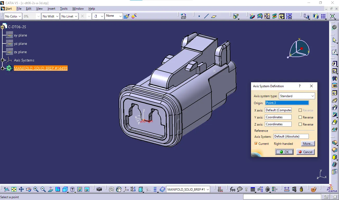 Switch to 'Electric Part Design'
 - Define the part as connector in catia, give no. of termination as 2 because we have 2 entry points for wire.
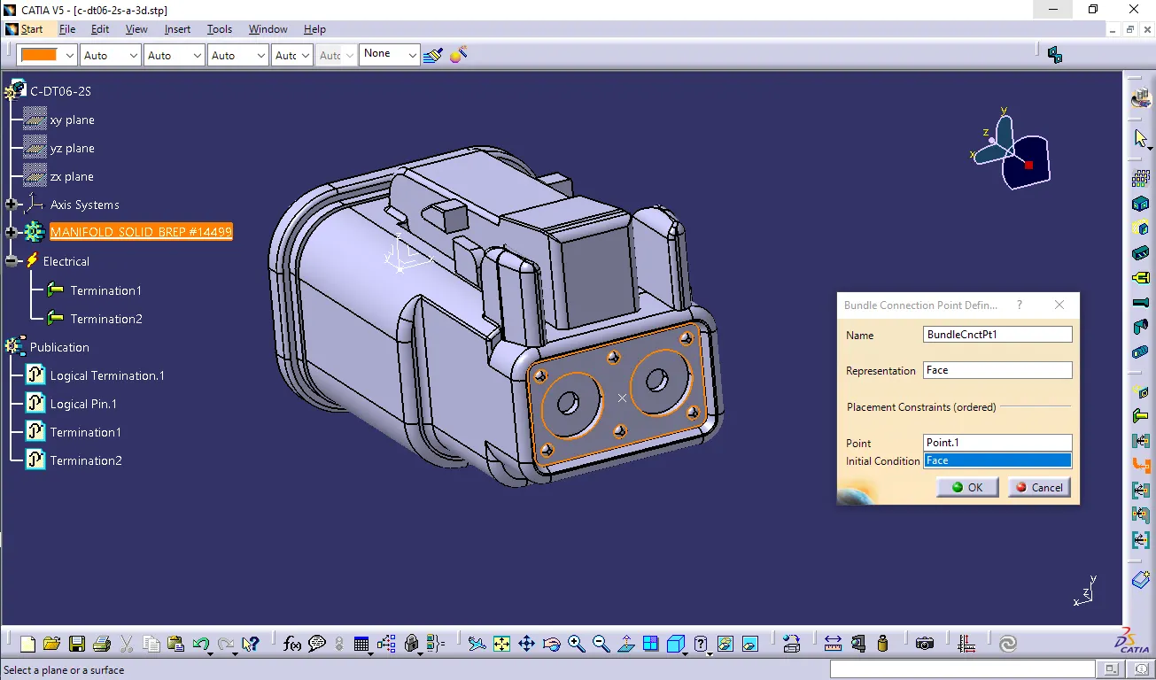
- Bundle connection point:
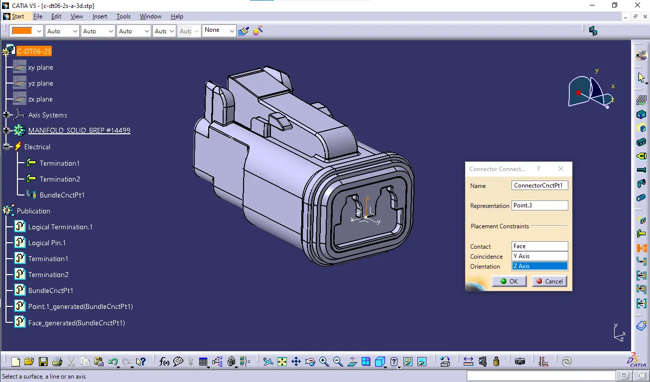
- Connector connection point:
 2. DT06-4S
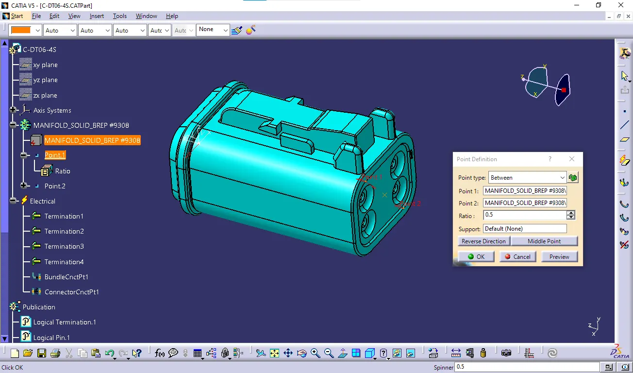
 - Create midpoint on the contact face which will be normal to wire bunddle insertion.
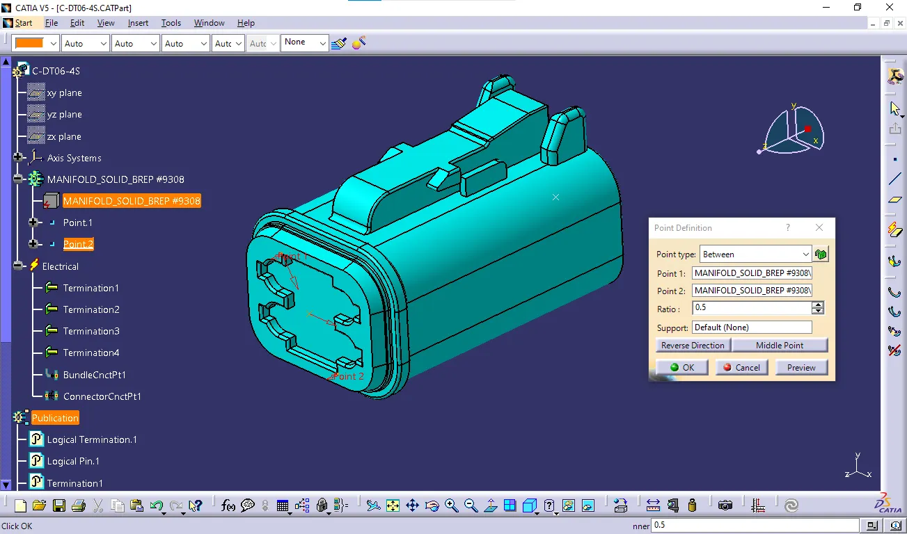
- Create Axis System with respect to the point which we have created and defining the axis direction as shown below.
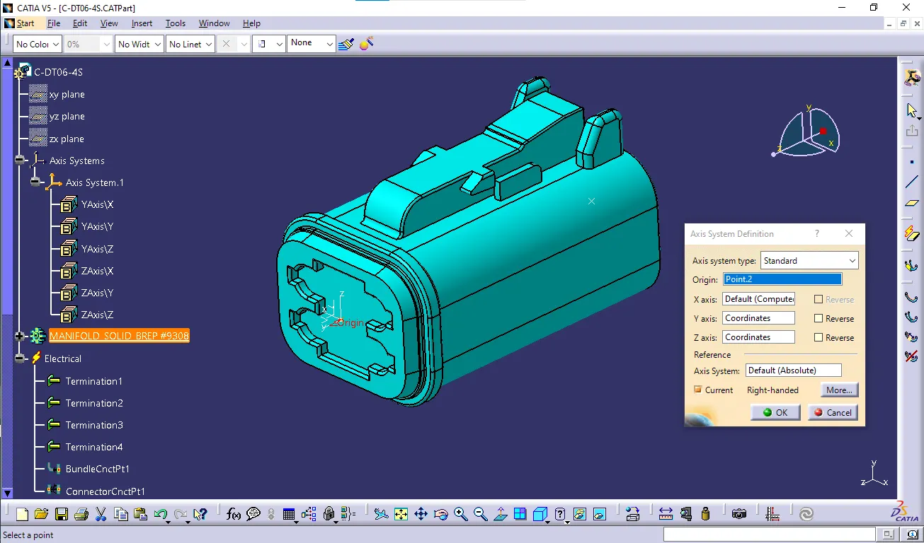 Switch to 'Electric Part Design'
- Define the part as connector in catia, give no. of termination as 4 because we have 4 entry points for wire.
- Define Bundle connection point
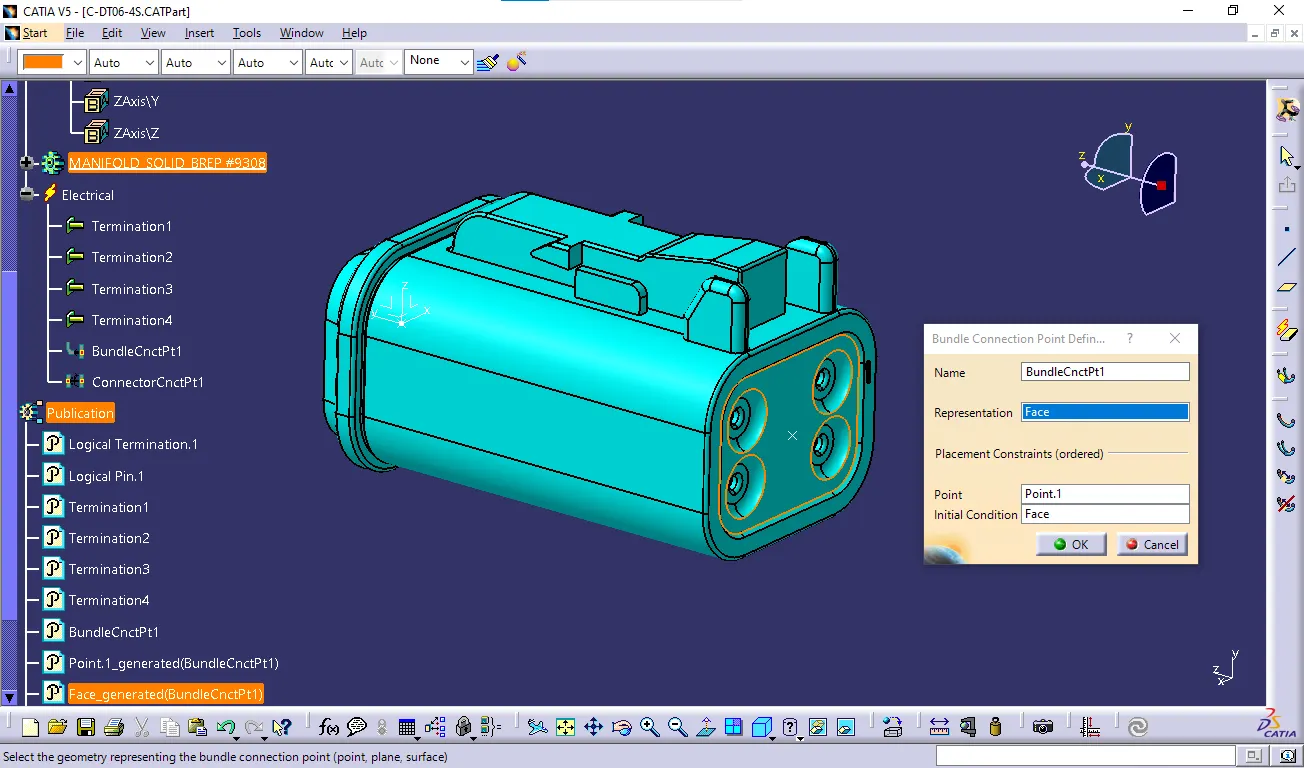
- Define connector connection point
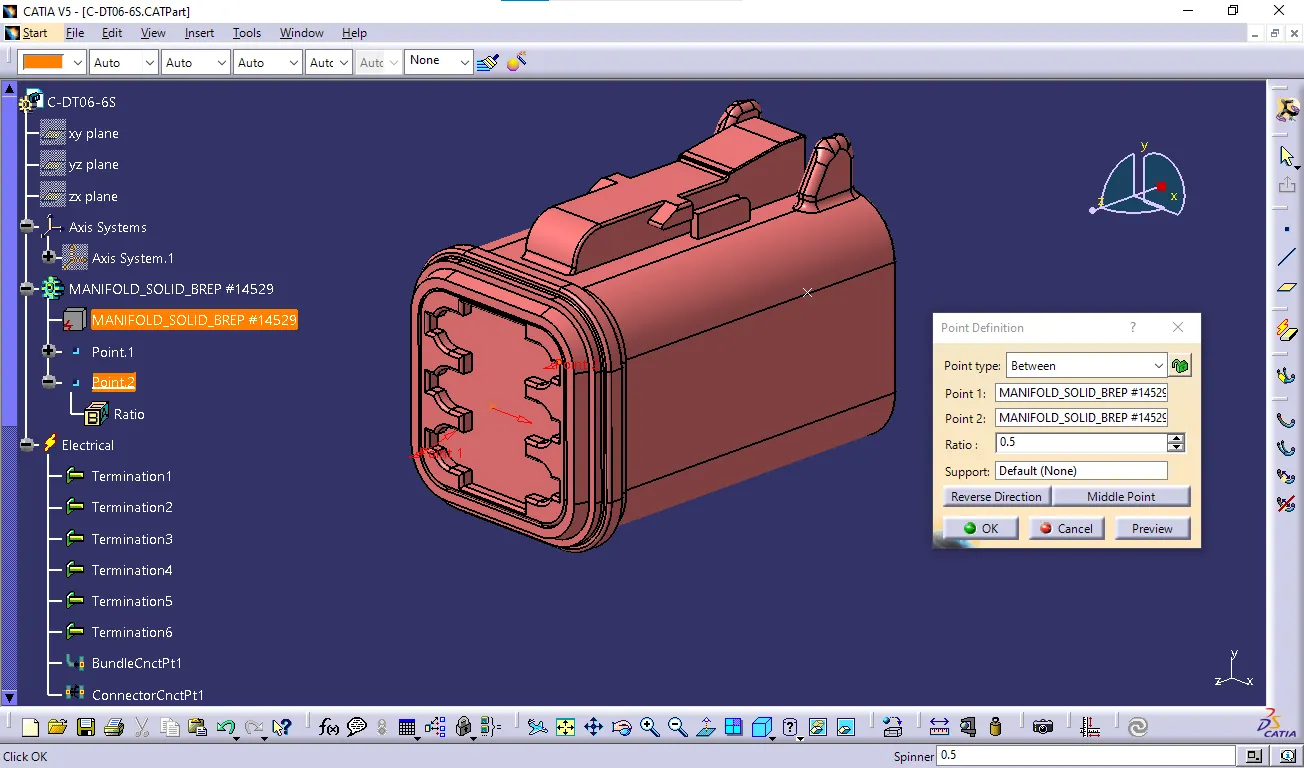
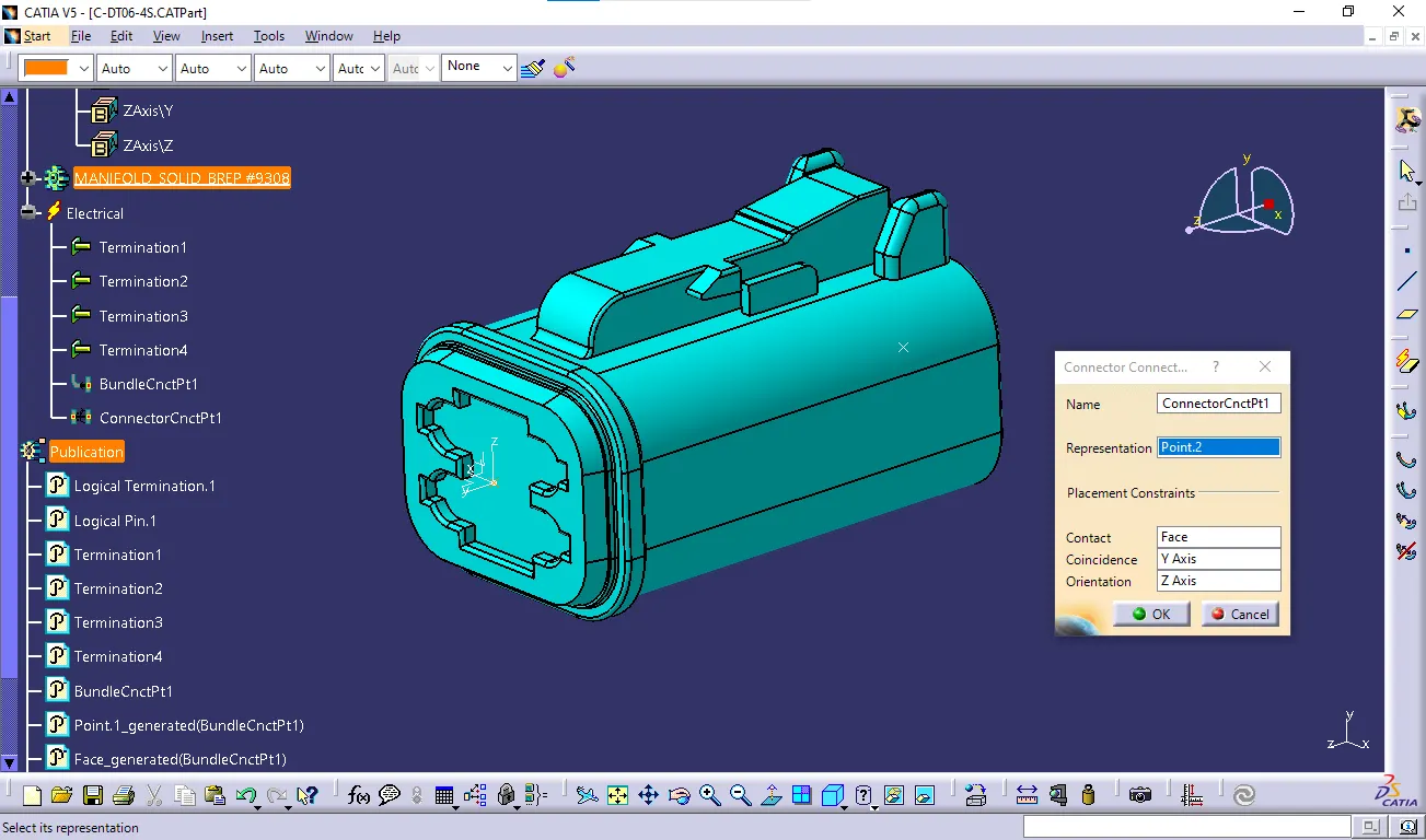 3.DT06-6S
 - Create midpoint on the contact face which will be normal to wire bunddle insertion.
- Create Axis System with respect to the point which we have created and defining the axis direction as shown below.
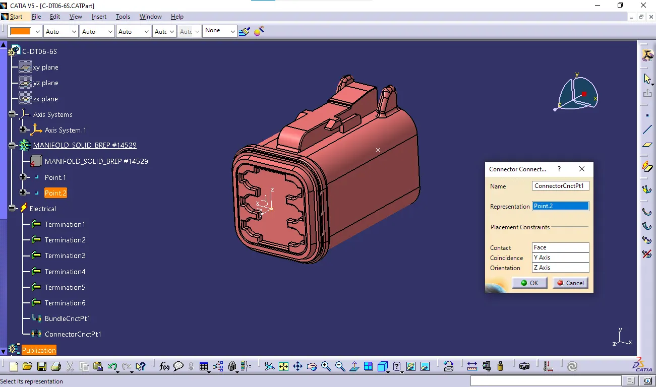
- Switch to 'Electric Part Design'
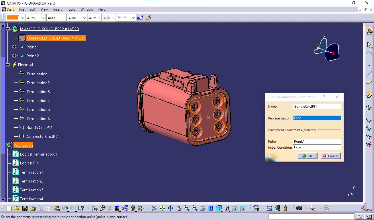
- Define the part as connector in catia, give no. of termination as 6 because we have 6 entry points for wire.
- Define Bundle connection point
- Define connector connection point
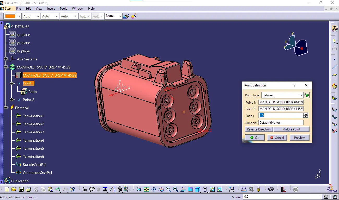
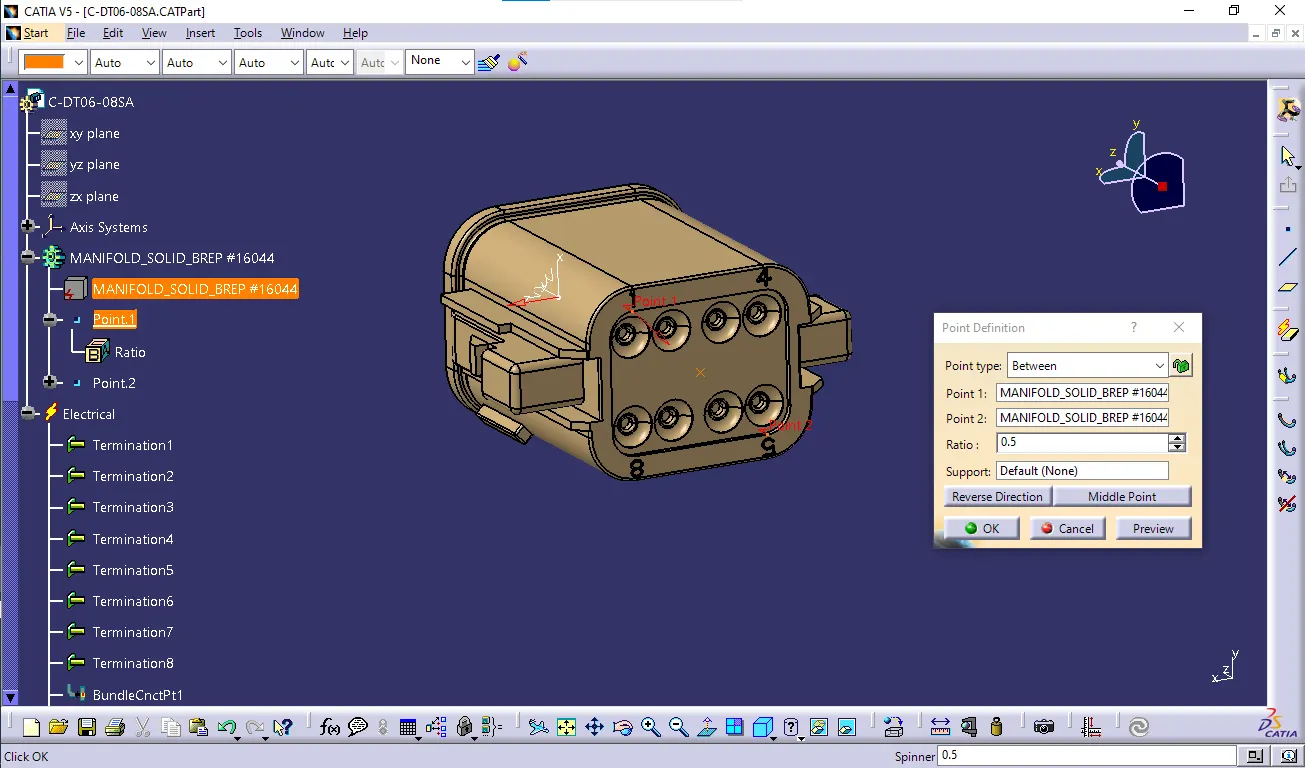
- 4.DT06-08SA
- Create midpoint on the contact face which will be normal to wire bunddle insertion.
- Create Axis System with respect to the point which we have created and defining the axis direction as shown below.
- Switch to 'Electric Part Design'
- Define the part as connector in catia, give no. of termination as 6 because we have 6 entry points for wire.
- Define Bundle connection point
- Define connector connection point
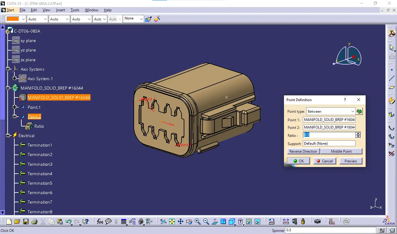
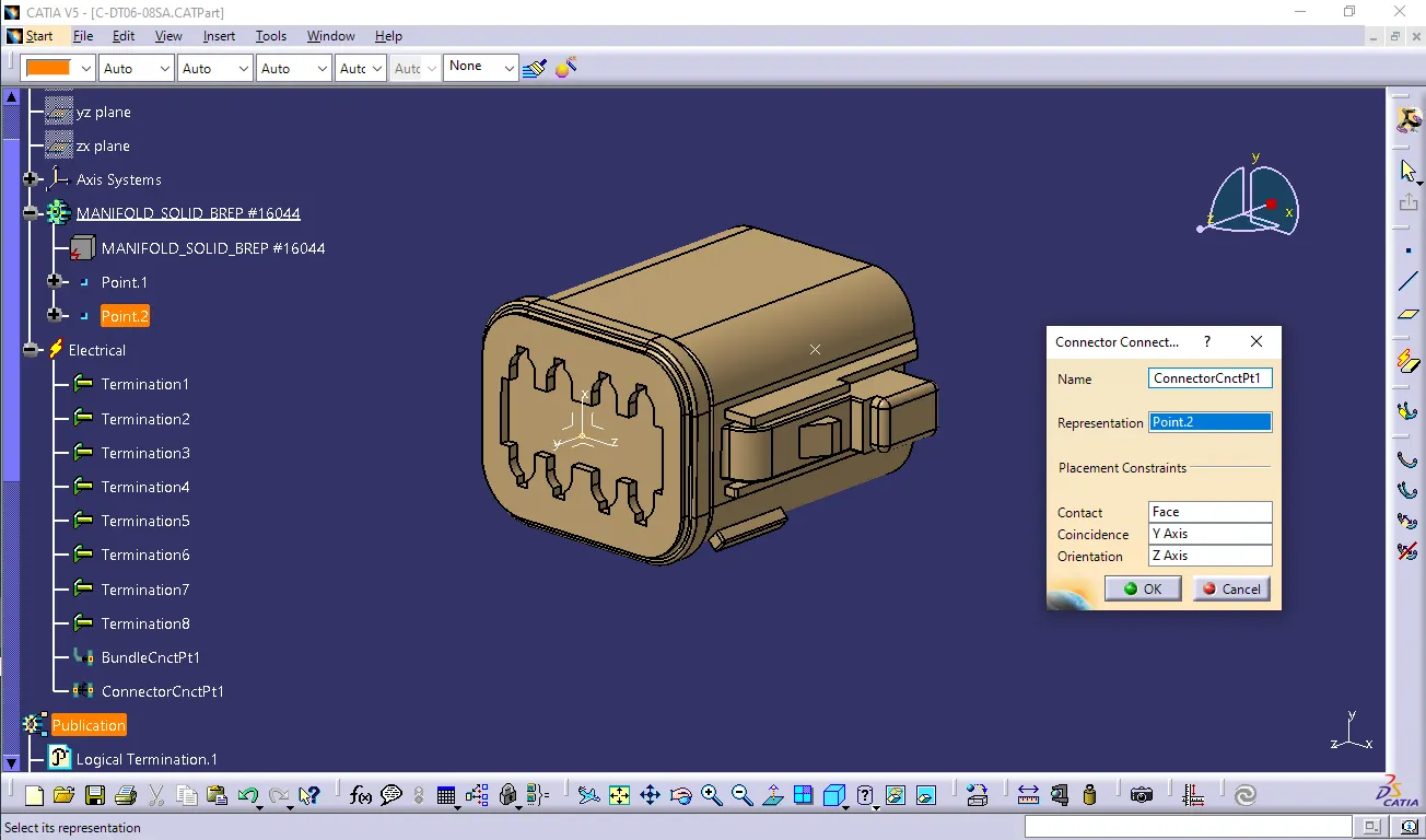
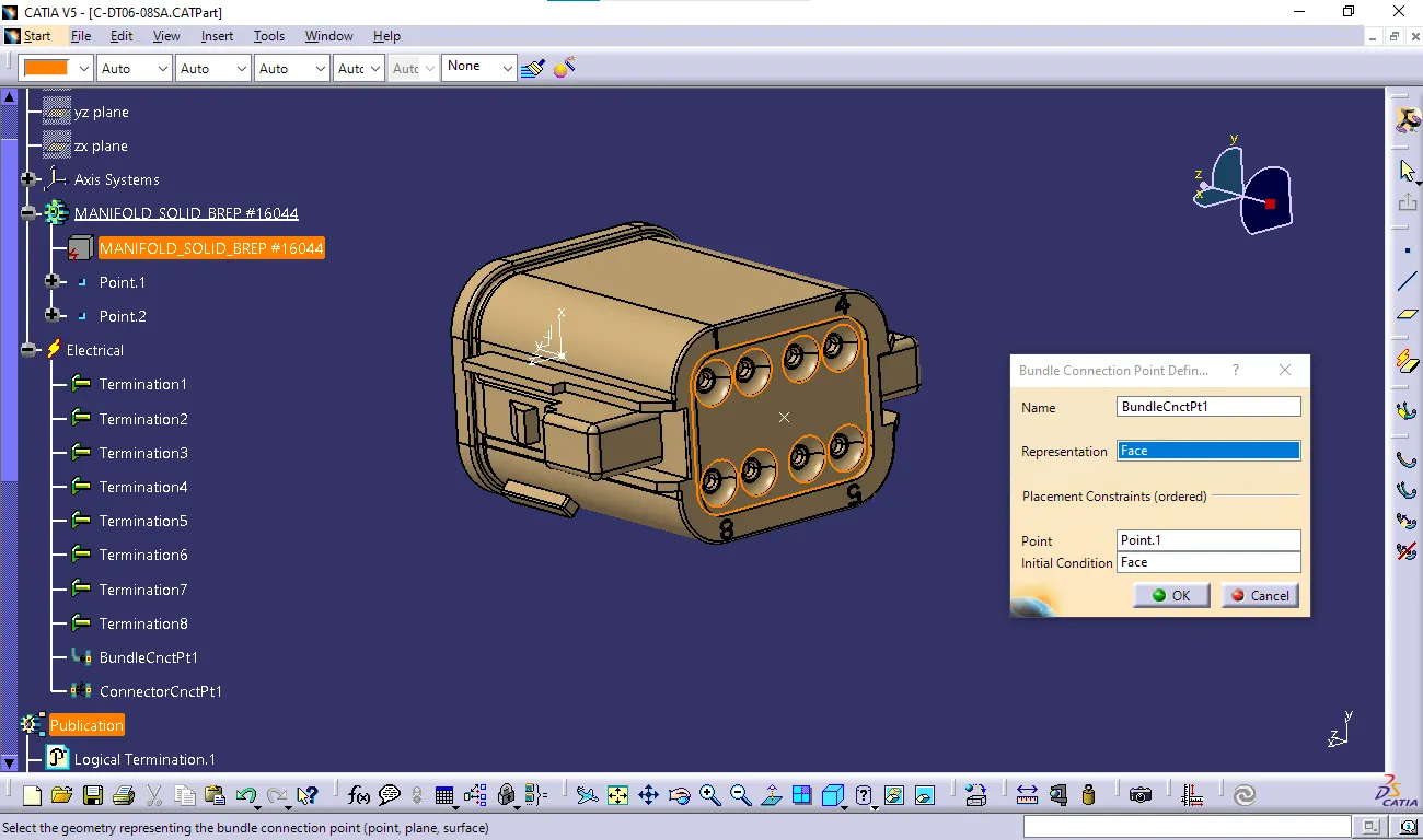
-
Product
- Open a new product file and imported all the defined models into it.
- Draw a sketch as required.
- Using snap arranging the Connectors by following the Layout.
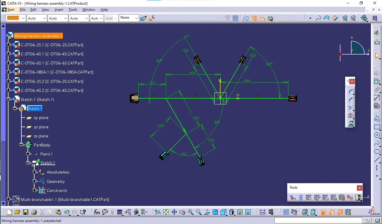
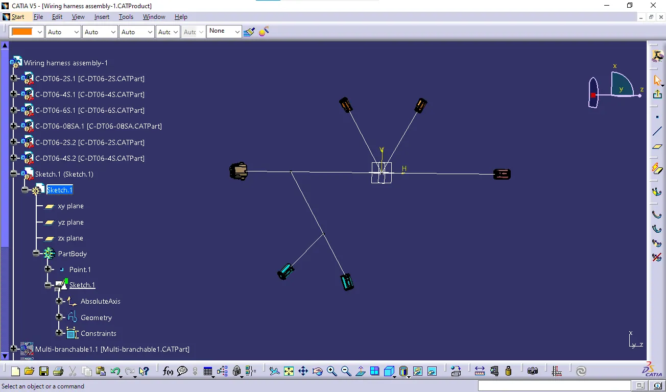
- Creating Multi-Branching to the connectors
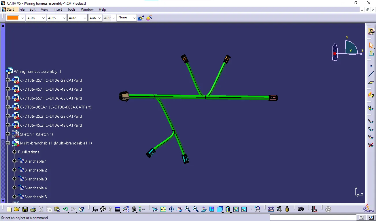
- creating a protective covering