Wiring harness design in CATIA V5 - 3D modeling Week 4 Challenge
Report
The necessary CAD information of the connectors is obtained from the te.com website. These files are initially in the .step format and are then accessed using CATIA software. Once opened, these files represent models of the connectors, which are then converted and saved as .CATPart files in a designated folder. To integrate an electrical component into the harness routing assembly, it must first be given electrical attributes. Since the component is initially designed as a mechanical part, it needs to undergo a transformation into an electrical part. Before this transformation, certain attributes need to be established, including connector connection points, connector connection axes, bundle coaction points, cavity connection points etc.
Creating Geometrical parameters:
The CAD data retrieved for the connectors should be included with important geometric characteristics like the Connector Connection Point, Connector Connection Axis, Bundle Connection Point, and Cavity Connection Point. It's important to highlight that the creation of the cavity connection point is contingent upon the presence of a clip mounting feature within the connector. Consequently, these geometric attributes are generated within the 'Part Design' workspace of the Mechanical environment.
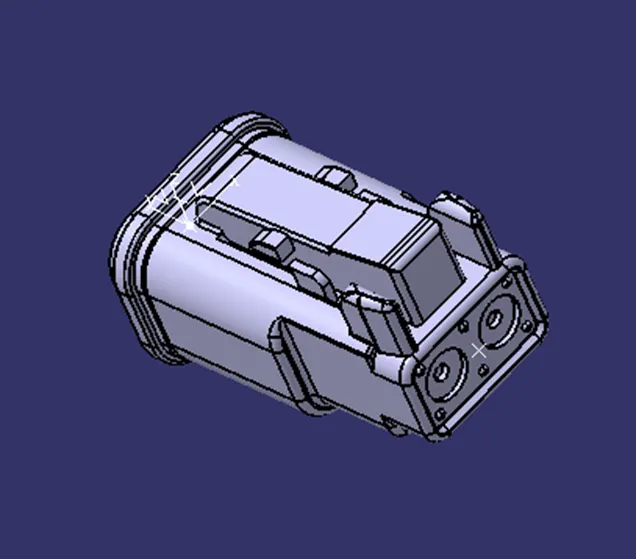
- DT06-2S
Connector Connection Point
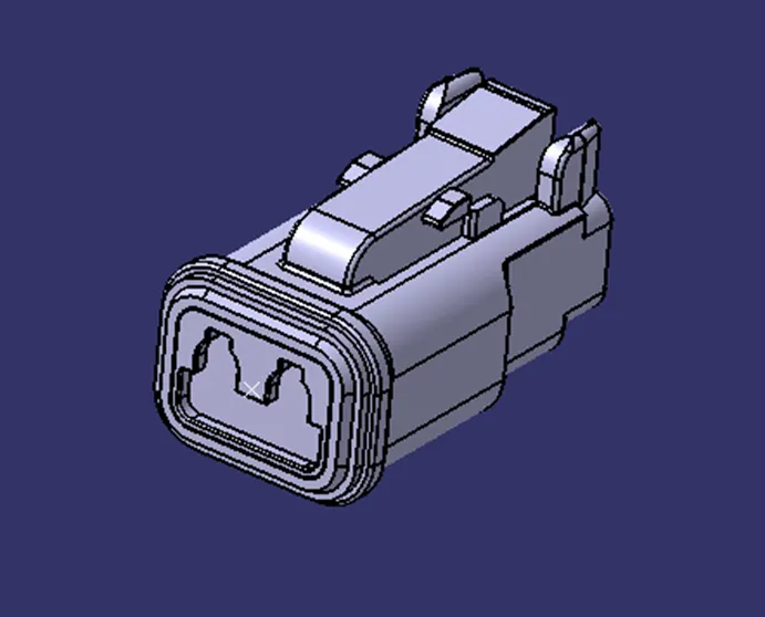
Connector Connection Axis
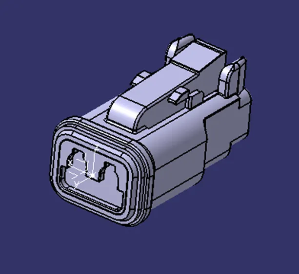
Bundle Connection point
- DT06-4S
Connector Connection Point
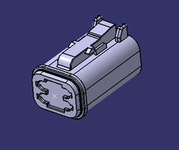
Connector Connection Axis
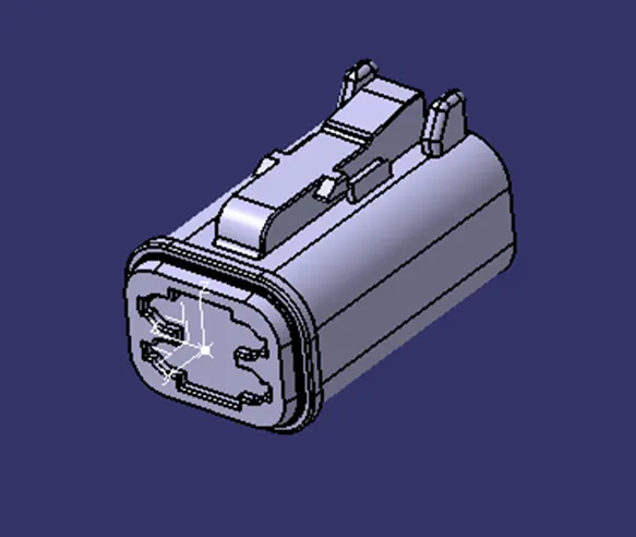
Bundle Connection point
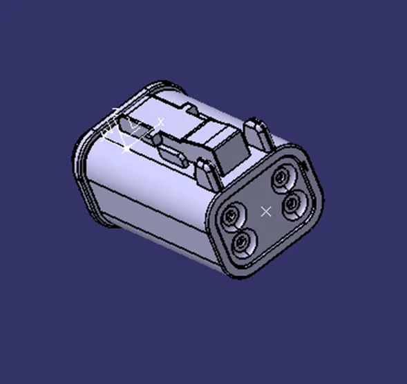
- DT06-6S
Connector Connection Point
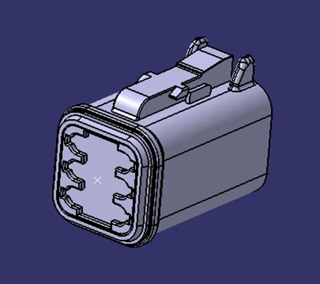
Connector Connection Axis
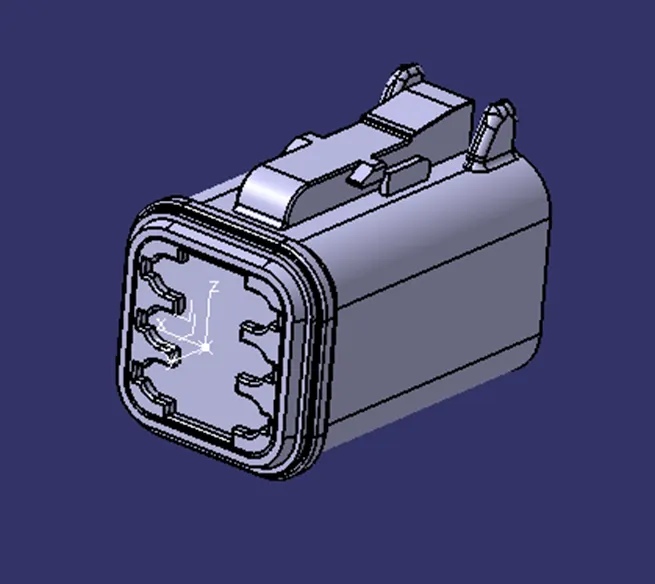
Bundle Connection point
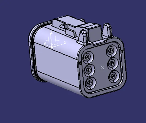
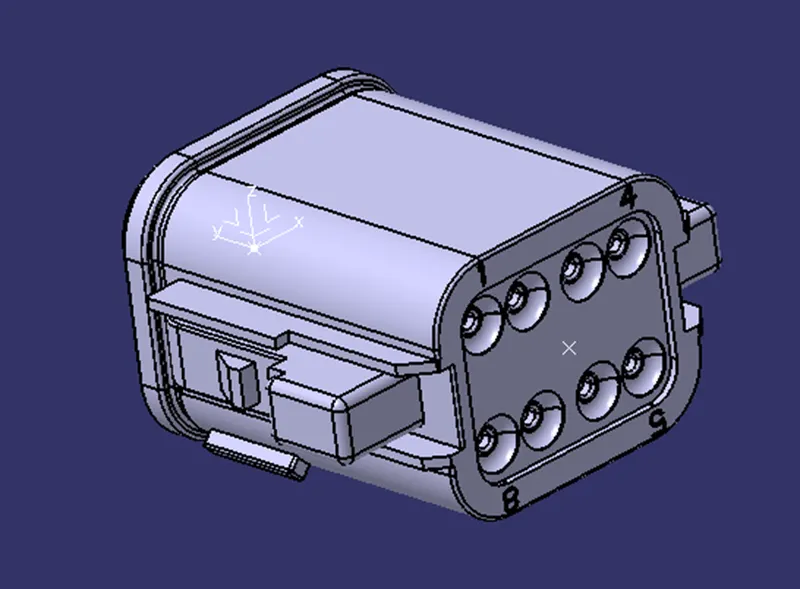
- DT06-08SA
Connector Connection Point
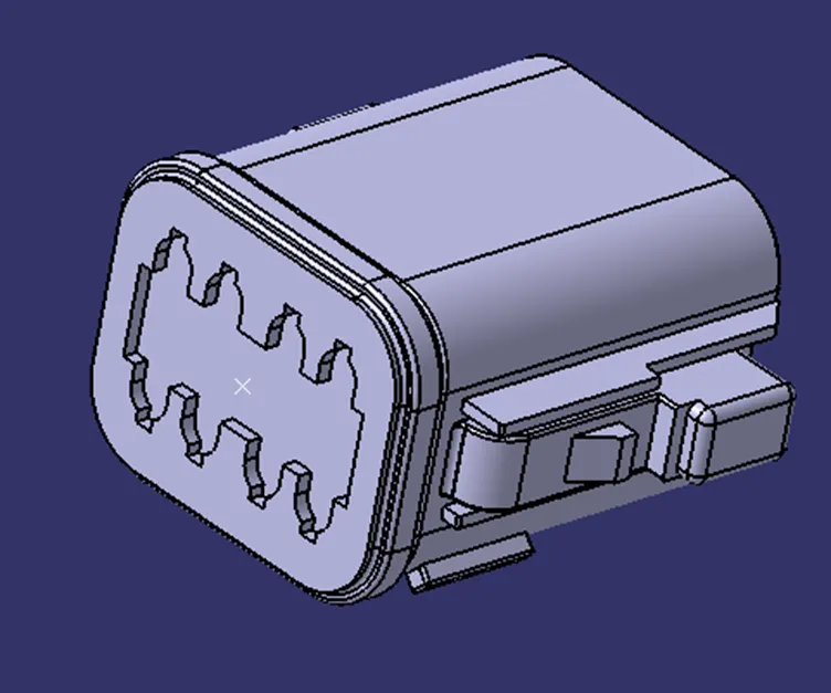
Connector Connection Axis
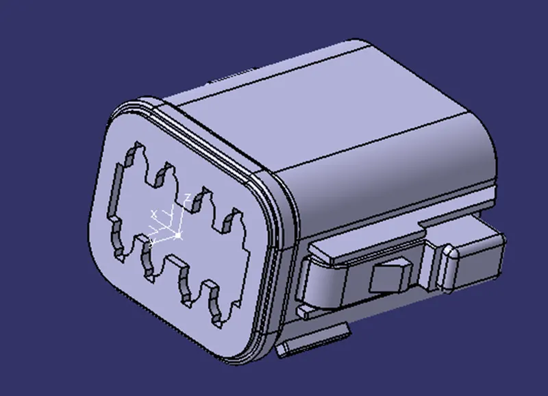
Bundle Connection point
Wiring Harness Routing Assembly
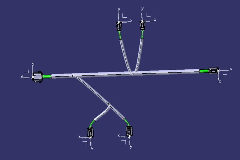
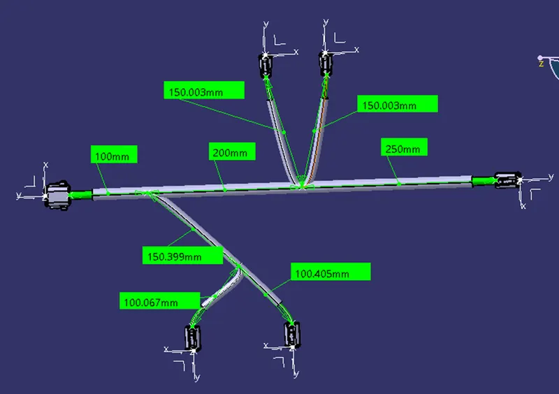
To create the wiring harness routing assembly, firstly the parts necessary for the routing are brought into an assembly file and then all the parts are placed in their intended position within the assembly. Then a multi-branchable document is created through which the various components of the assembly are bundled together. The bundle layout is created automatically based on the position of the two components selected at a time and the relevant bundle diameter is applied during the due procedure.
Placement of Assembly Components:
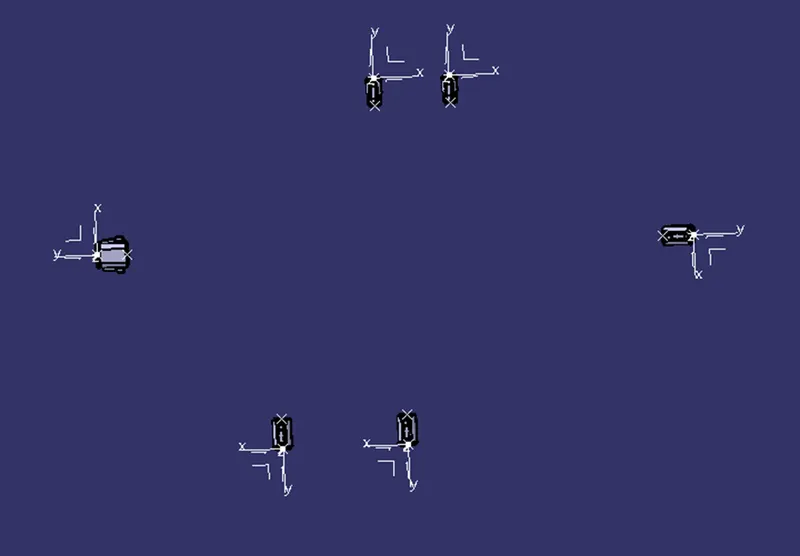
Multi-Branchable Document
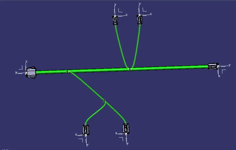
Protection Covering