Week 8 - Challenge 2 - Switch Bezel Design
|
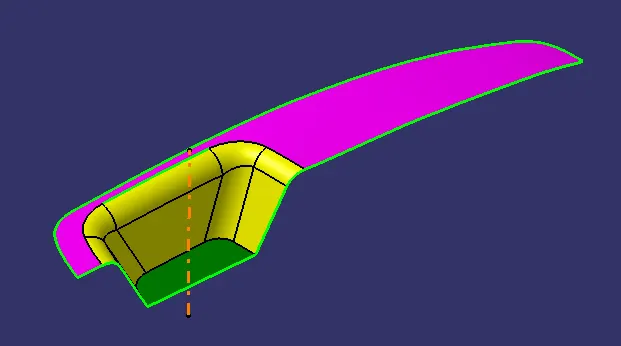
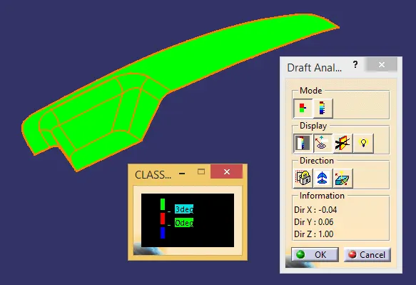
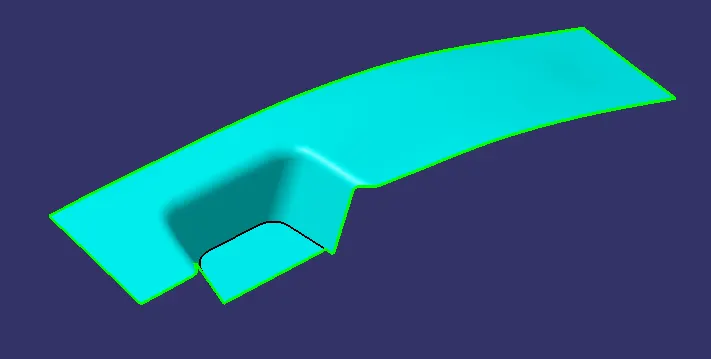
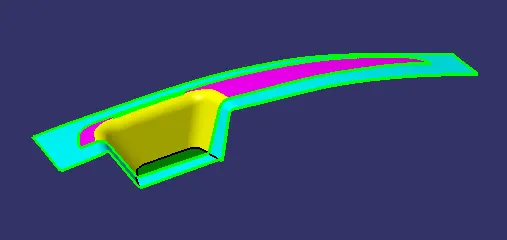
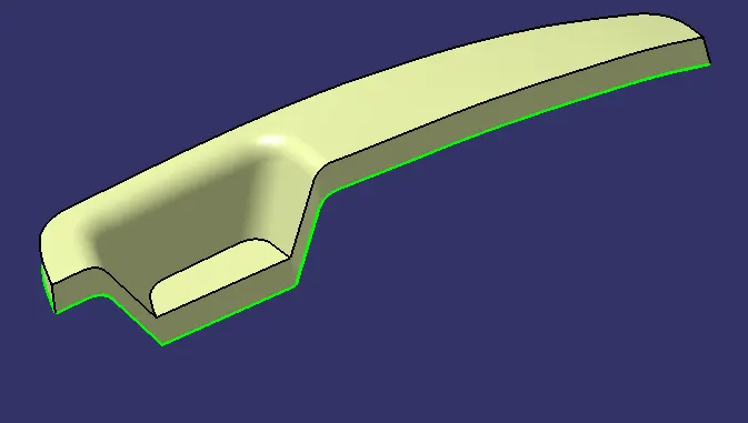
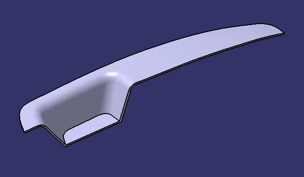
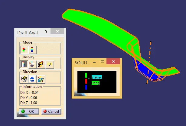
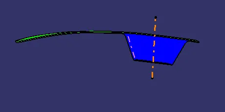
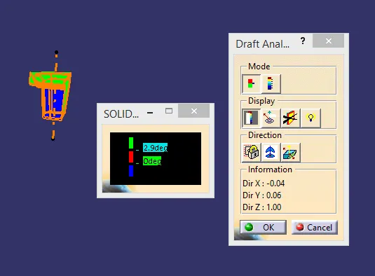
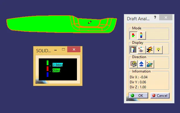
AIM: To create the Switch Bezel plastic component through the given class-A surface. Introduction: Switch Bezel is an interior component of an automobile which usually is the part that also doubles up as an arm rest that is attached to the door of the vehicle. It is mostly a plastic component as any other part in the cabin of an automobile. Plastic products are mainly produced through injection molding. Injection molded parts have two sides: the A side, which faces the cavity and the B side, which faces the core. These two sides usually serve different purposes. The A side usually has better visual appearance and is often called the cosmetic side. The faces on the A side will be smooth or will have a texture according to the design specifications. The B side usually contains the hidden structural elements of the part. For this reason it is called the functional side. The B side will often have a rougher finish and visible marks from the ejector pins. A plastic designer usually gets the A surface as an input and then his/her job is to carry out the necessary draft analysis on the class-A surface considering the requires draft angle and then design the class-B, class-C and subsequently arrive at the actual solid CAD part model of the required component. Creating Tooling Axis (by Bisection Method) The given class-A surface of the switch bezel has some flat surfaces with fillets at some of the edges of the cup portion of the surface. The tooling direction can be taken in the z-direction and the main tooling axis lies in the cup portion of the surface as it consists of parallel faces in the z-direction. To arrive at the tooling axis for the given surface firstly a point is created at the center of the surface that forms the bottom of the cup portion of the class-A. Then the cross section of the component at the created point is taken in both the directions other than the tooling direction (x and y-direction in this case). Then the faces that are parallel to the tooling direction are projected as lines and a bisecting line is created between them passing through the point created initially. This bisecting line forms the temporary tooling axis in the respective direction. The bisecting line is created in both the above said directions. If the two bisecting lines do not coincide then these two lines are again bisected as they pass through the same point and the line obtained will be the ‘Tooling Axis’. Draft Analysis on Class-A Surface During the production of plastic components in the mold, first the plastic is heated into molten form and then injected into the mold cavity. After the plastic cools down inside the mold cavity, it solidifies and forms the component. During this cooling period, the plastic has the tendency to shrink causing it to stick to the mold wall and makes it harder to eject from the mold cavity. Hence the plastic design engineers have to consider the draft angle to all vertical surfaces. To do the draft analysis the view mode is changed by keeping the ‘Materials” option active inside the ‘Customize View’. Then under the ‘Insert’ tab we select ‘Feature Draft Analysis’ under the ’Analysis’ section. First the new current draft direction is set by adjusting the compass to the tooling axis. This is done by selecting the second icon under the ‘Direction’ section in the ‘Draft Analysis’ tab. After adjusting the compass the draft direction is locked in position by selecting the first option under the ‘Direction’ section. The cursor then is hovered on the class-A surface and clicked upon when a cross symbol is seen. Then the class-A surface turns to any of the three colors (green, blue or red). In the color coded dialog box, the minimum draft angle is set and the analysis is carried out. If the color of the surface is satisfactory according to the values entered in the dialog box then the draft analysis is concluded. Creation of Class-B Surface To create the Class-B surface for the given input, all the flat surfaces present in the class-A are extracted excluding the filleted surfaces if any. The extraction is done using the ‘Extract’ option in the ‘Generative Shape Design’ workbench. Then the extracted surfaces which were created by trimming a previously created surface to obtain the class-A are untrimmed using the ‘Untrim’ option in the toolbar and also later the ‘Extrapolate’ option is used to to extend the untrimmed surfaces such that all the surfaces come in contact with one another. Later using the ‘Trim’ option the surfaces are trimmed such that the resulting surface resembles the class-A. Then the required curves at the edges of two surfaces are craeted using the ‘Edge Fillet’ option. Finally the optained surface is moved through a distance equalling the thickness of the compont towards the B-side using the ‘Offset’ option. Thus this offset surface is the required class-B surface. Creation of Class-C Surface Class-C is a non-aesthetic suraface which connects the class-A and class-B surfaces. Class-C is often specified for interior surfaces not readily visible, surfaces that will be covered by another part when assembled or surfaces which the customer feels do not need to meet a high cosmetic finish. To create the class-C surface, the boundary of the class-A is taken using ‘Multiple Extract’ option with tangent continuity of the curve. Then the surface is created using the curve along the tooling direction. If there are multiple curves that are extracted using the tangent continuity, then the surfaces created from each extacted boundary are joined together such that the resulting surface forms the class-C surface. Creation of Solid CAD Component To create the solid CAD component we need to have a closed surface resembling the actual component. To get the closed surface we need to first join the class-A with the class-C surface. Then this joined surface and the B-surface are trimmed off to get the required clsoed surface. Then in the ‘Part Design’ Workbench the closed surface is filled using the ‘Close Surface’ option in the toolbar. The resulting part is the required solid CAD component. Draft Analysis on CAD Model Draft Analysis on the CAD component is carried out in the same manner as that on the class-A surface to check if the component can be ejected from the mold in the injection molding machine.
|