Week 8 - Challenge 1 - Base Bracket Design
|
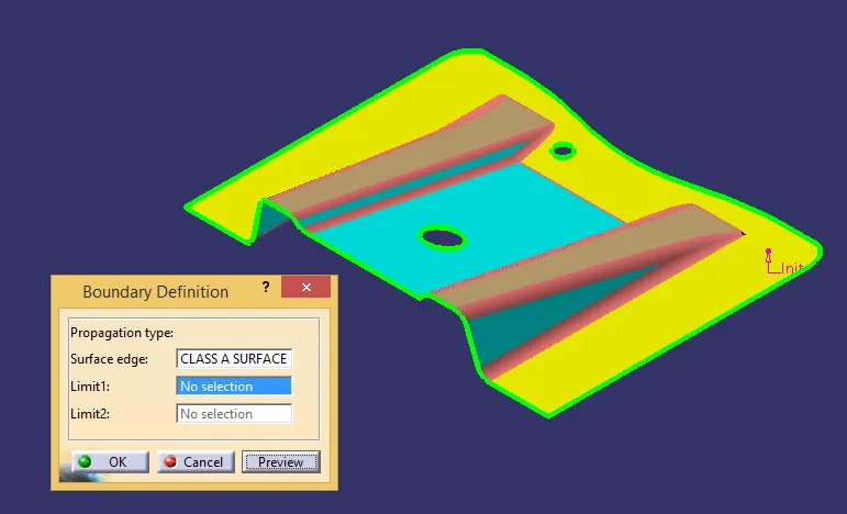
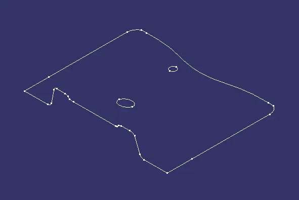
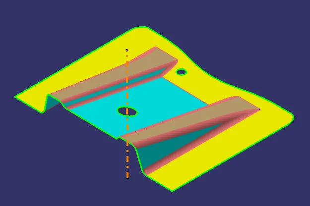
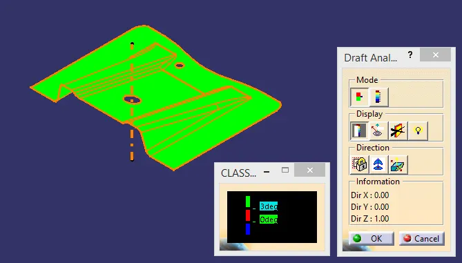
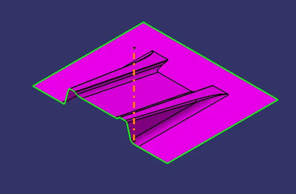
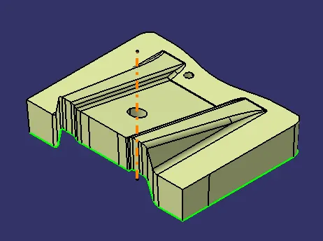
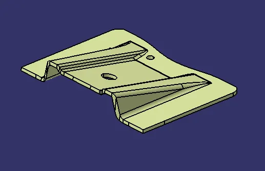
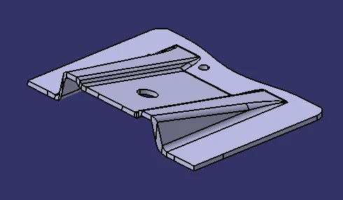
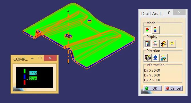
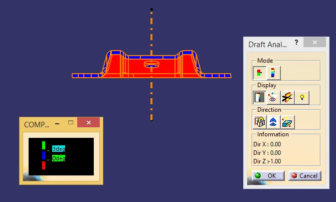
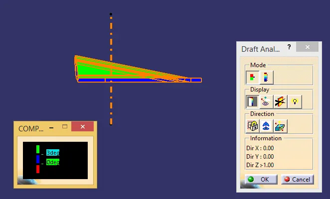
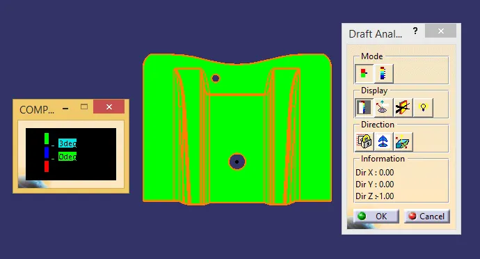
AIM: To create a Base bracket plastic component from a given class-A surface. Introduction: A bracket is a component which acts as a support for load bearing or attachments to a structural element. The component to be designed is of plastic composition. To design any component with irregular or complex geometries we need to have a Class-A surface of the component to be designed as input. The given surface is subjected to draft analysis to check if it can be produced in an injection mould with the required draft angle. Then from the class-A surface we create a class-B surface by offsetting the input surface to the required thickness value. Then the Class-C surface is created from the given input class-A surface and all the surfaces are joined together to form a closed surface model of the final component. This closed surface is filled to form the solid component. A final Draft analysis on the solid CAD component is carried out similar to the analysis done on the class-A surface. All these design procedures are carried out in the ‘Generative Shape design’ and the ‘Part Design’ workbenches of the CATIA-V5 software. Check class-A surface A class-A surface is any of a set of freeform surfaces of high efficiency and quality. It describes the final production surface data for the aesthetic parts of a component. To create the required component from the class-A surface the ‘Generative Shape Design’ workbench in the CATIA V5 software is used. After receiving the Class A as an input, it is first checked for any discrepencies and made sure that it has good curvature continuity. This can be checked with the help of the ‘Boundary’ option in the toolbar which when enabled and checked for, creates a boundary around the outside edge of open areas in the surface. This way we can check the quality of the given surface and proceed if there are no errors. Creation of tooling axis After carefully analyzing the component we arrive at the proper tooling axis. Tooling axis represents the direction in which the mould acts in the moulding machine and also the direction in which the component is ejected from the mould. It should be created by considering the draft angle. To create the tooling axis usually a flat surface or a hole in the component is preferred. After choosing the proper position, an intersection is created between the class-A surface and the axis at that position to which there are perpendicular surfaces in the class-A. Then lines are created along such faces that are parallel along the assumed tooling direction and a bisecting line of these projected lines at the intended point is created which represents the tooling axis. Draft analysis on class-A Then the draft analysis on the class-A surface is carried out. It is used to analyze whether the given surface is manufacturable under the draft condition that is applied for the creation of part model from the given surface. Ideally for plastic components a draft angle between 3°-10° is applied. Firstly the view mode is changed by keeping the ‘Materials” option active inside the ‘Customize View’. Then under the ‘Insert’ tab we select ‘Feature Draft Analysis’ under the ’Analysis’ section. First the new current draft direction is set by adjusting the compass to the tooling axis. This is done by selecting the second icon under the ‘Direction’ section in the ‘Draft Analysis’ tab. After adjusting the compass the draft direction is locked in position by selecting the first option under the ‘Direction’ section. The cursor then is hovered on the class-A surface and clicked upon when a cross symbol is seen. Then the class-A surface turns to either of the three colors (green, blue or red). In the color coded dialog box, the minimum dreaft angle is set and the analysis is carried out. If the color of the surface is satisfactory according to the values entered in the dialog box then the draft analysis is concluded. Creation of Class-B surface Then the B surface is created from the given class-A surface by offsetting the class-A surface elementarily considering flat surfaces in it. A class-B surface is a secondary surface which is not seen by the eye when we see a component such as the inside of a glove box, lower surface of the base bracket etc. Tools such as extract (or multiple extract) are used to isolate flat surfaces from the given class-A and then these isolated surfaces are untrimmed using the ‘untrim’ option. Then they are enlarged such that they all coincide fully with each other using the ‘extrapolate’ option. Then these surfaces are trimmed such that they resemble the faces on class-A from which they were extracted. Then they are offset to a value equal to the thickness of the component. Same procedure is done for all the flat surfaces in the class-A until the entire surface is offset to the required value. Then the fillets are provided wherever necessary. At last the surface we obtain is the required class-B surface. Creation of class-C surface After the creation of class-B surface the C surface is created from the boundary of the given class-A surface. The C surface connects the class-A to the class-B surface and usually represents the thickness of the component. To create the C surface the boundary of the class-A is isolated using the ‘Boundary’ option. Then using the ‘Sweep’ option the C surface is swept along the tooling direction and the required draft angle. Creating the solid Component All the three surfaces are trimmed to form a closed surface representing the actual component. Then the closed surface is thickened or filled using the ‘Close Surface’ option in the ‘Part Design’ workbench of the software to form the required solid CAD model of the component. Then carryout the draft analysis on the solid component the same way as did on the class-A surface. |