Week 8 - Challenge 4 - Bumper
|
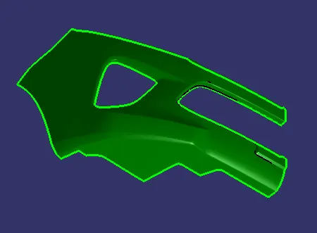
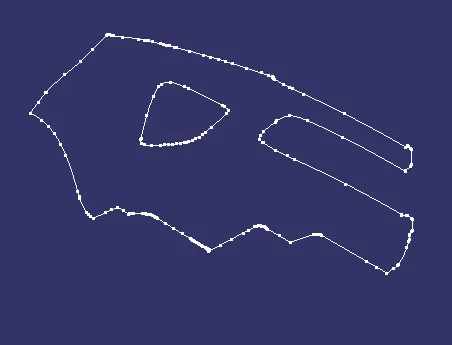
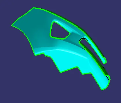
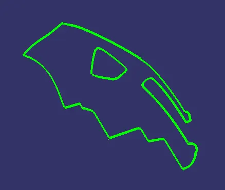
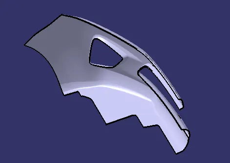
AIM: To create the Bumper Plastic component from the given class-A surface. Introduction: A car bumper is an external feature of a car usually made of high quality plastic designed to absorb impact to the front and rear end of the vehicle to minimize low-speed collision damages. In this exercise I have been given a class-A surface of a car bumper and am required to design the actual solid CAD component of the same using the given input surface and also carry out the draft analysis both on the given class-A and the solid component to validate the design for manufacturing. Checking Given Class-A Surface: Initially while designing any component from a class-A surface, the given surface should be checked for its quality by looking for unwanted gaps in the surface in the form of open boundaries. This can be checked by using the ‘boundary’ option from the toolbar which shows the boundary of the input surface. If there is any discontinuity in the given surface or open boundary in between it could be easily made out and corrected accordingly working concurrently with the class-A design engineer.
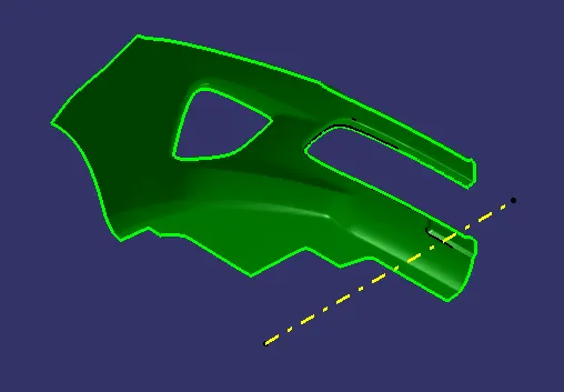
Creating Tooling Axis (by Bisection Method): The given class-A surface of the bumper component is a complex one with a lot of curved surfaces. By closely analysing the input surface it can be found out that the tooling direction can be taken in the x-direction. So consider any point on the class-A surface and create a line in the x-direction using the ‘line’ command from the toolbar.
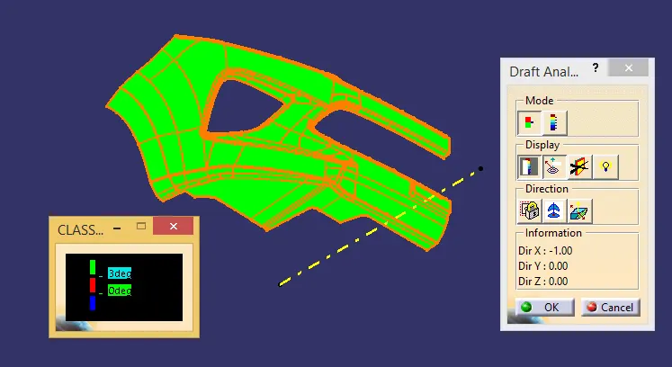
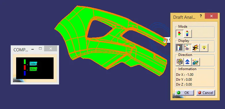
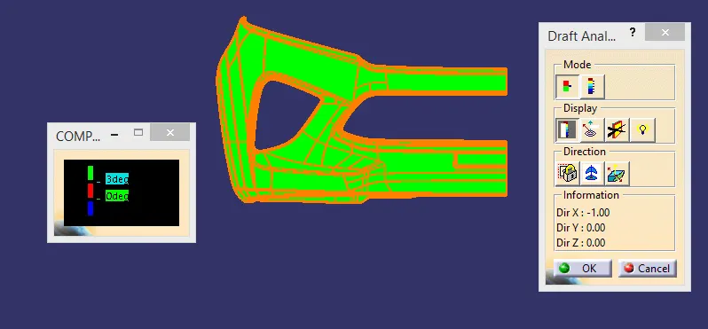
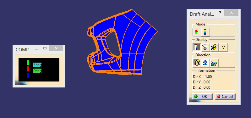
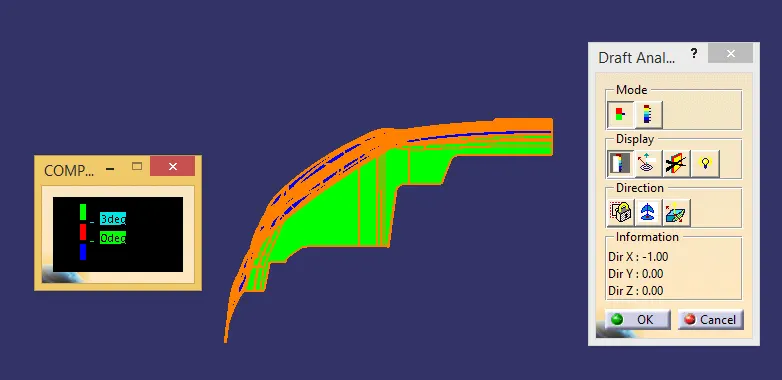
Draft Analysis on Class-A: Draft analysis on the given class-A surface is carried out. This is done in the ‘Generative Surface Design’ workbench under which the ‘Customize View Parameter’ is set to the ‘Material’ mode. Then from the ‘Inset’ tab, ‘Draft analysis’ tool is selected from the ‘Analysis’ section and then the required draft angle is set with respect to the tooling axis created and the draft analysis is carried out.
Creation of Class-B Surface: To create the class-B surface for the given input surface, the entire surface is offset to a distance equivalent to the thickness of the component. As the bumper component has complex curves with almost no flat surfaces, it is offset in its entirety at once. But still some parts of the class-A surface fail to offset to the required length due to some computing errors. Such parts can be corrected in two ways. Either they are extracted from the input surface and then offset individually. Later they are added to the initially offset surface. Else some surfaces which have a base surface with guide curves can be swept to obtain the closed surface. After finishing all the missing surfaces the obtained surface will be the required class-B. Creation of Class-C Surface: The class-C surface is created by sweeping from the curves in the class-A with tangent continuity along the tooling direction by considering required draft angle. All the swept surfaces are then joined together which forms the required class-C surface.
Creating Solid CAD Component: First the input surface and the class-C surfaces are added together and the protruded portions if any are trimmed off. Then the class-B surface is trimmed off from the previously obtained surface and then all are joined to form a closed surface of the component. This closed surface is filled using the ‘close surface’ feature from the toolbar to obtain the required solid CAD component.
Draft Analysis on the Solid CAD Component: Then the draft analysis on the solid component is carried out the same way as did on the class-A surface.
|