Week 8 - Challenge 3 - Coin Holder Design
|
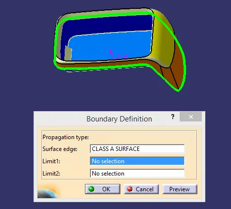
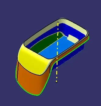
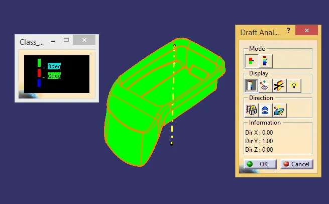
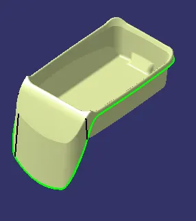
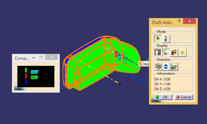
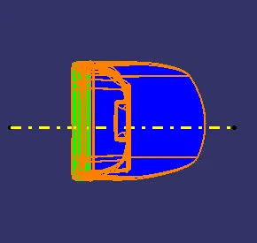
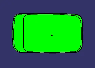
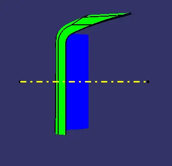
AIM: To create the coin holder plastic component from the given class-A component. Checking given class-A surface: Initially a plastic designer receives a class-A surface as an input to design a particular component. The given class-A surface is first analyzed for any errors such as open boundaries which may create problems while designing. If there are any errors then it may be requested upon the class-A designer to be checked upon and get corrected. This can be checked by choosing the ‘Boundary’ option from the toolbar in the ‘Generative Shape Design’ workbench and then clicking on the input surface. This way it can be found out if there are any open boundaries in between the surface. If the surface is error-free then we carry on with designing the component. Creating Tooling Axis (by Bisection Method): Tooling axis represents the direction in which the component is ejected from the mold. It should be created by considering the draft angle. To create the tooling axis usually a flat surface or a hole in the component is preferred. After choosing the proper position, an intersection is created between the class-A surface and the axis at that position to which there are perpendicular surfaces in the class-A. Then lines are created along such faces that are parallel along the assumed tooling direction and a bisecting line of these projected lines at the intended point is created which represents the tooling axis. In the coin holder, it can be seen that the tooling axis can be created in the y-direction. The final tooling direction is arrived by bisecting the lines that are projected from the surfaces parallel to the y-direction in both x- and z-directions. Draft Analysis on Class-A: Firstly the view mode is changed by keeping the ‘Materials” option active inside the ‘Customize View’. Then under the ‘Insert’ tab we select ‘Feature Draft Analysis’ under the ’Analysis’ section. First the new current draft direction is set by adjusting the compass to the tooling axis. This is done by selecting the second icon under the ‘Direction’ section in the ‘Draft Analysis’ tab. After adjusting the compass the draft direction is locked in position by selecting the first option under the ‘Direction’ section. The cursor then is hovered on the class-A surface and clicked upon when a cross symbol is seen. Then the class-A surface turns to any of the three colors (green, blue or red). In the color coded dialog box, the minimum draft angle is set and the analysis is carried out. If the color of the surface is satisfactory according to the values entered in the dialog box then the draft analysis is concluded. Creation of Class-B Surface: To create the class-B surface, all the flat faces of the surface excluding the fillets in it are extracted and then untrimmed. Later these surfaces are extrapolated such that they all intersect each other. Then these surfaces are trimmed and then the resultant surface is offset to a distance equal to the thickness of the component on the B-side of the component.
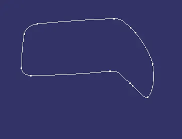
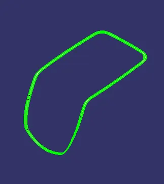
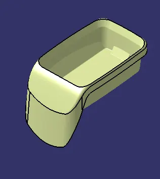
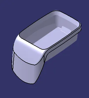
Creation of class-C Surface: After the creation of class-B surface the C surface is created from the boundary of the given class-A surface. The C surface connects the class-A to the class-B surface and usually represents the thickness of the component. To create the C surface the boundary of the class-A is isolated using the ‘Boundary’ option. Then using the ‘Sweep’ option the C surface is swept along the tooling direction and the required draft angle. Creating the Solid CAD Component: To create the solid CAD component we need to have a closed surface resembling the actual component. To get the closed surface we need to first join the class-A with the class-C surface. Then this joined surface and the B-surface are trimmed off to get the required clsoed surface. Then in the ‘Part Design’ Workbench the closed surface is filled using the ‘Close Surface’ option in the toolbar. The resulting part is the required solid CAD component. Draft Analysis on the Solid CAD Component: Then the draft analysis on the solid component is carried out the same way as did on the class-A surface. |