Wiring harness design in CATIA V5 - 3D modeling Week 4 Challenge
Aim:-
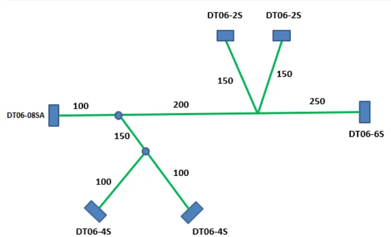
- Route the following harness layout in the electrical workbench. Make an assumption for harness bundle diameter. Use the following connection as shown in layout.
- Also, add protecting covering on all branches connected to DT06-2S & DT06-4S connectors. keep and extermily at 30mm.
- Download connector data from te.com
- DT06-4S
- DT06-6S
- DT06-2S
- DT06-08SA
Assign electrical properties to connector Steps:-
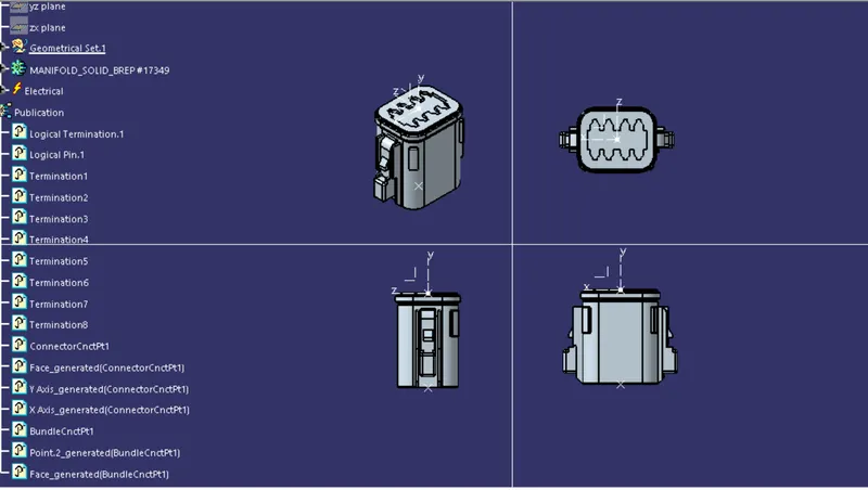
- The required connectors are downloaded from te.com.
- Gives axis system and point plotting on the face of the connector, inside part design workbench.
- Then go to electrical part design.
- Define the connector by using the CONNECTOR command.
- Respectively, define BUNDLE CONNECTION POINT & CONNECTOR CONNECTION POINT to a connector.
- Same step for other connector.
Creating wire harness:-
- Create the assembly of geometrical bundle products in CATIA V5.
- Open all the connectors into the geometrical bundle assembly product. Note that all the connectors must be electrically defined.
- Gives the exact positioning as per length to the connector by using SNAP, SMART MOVE, & MANIPULATION COMMAND.
- Now enter into 'wire harness assembly workbench'.
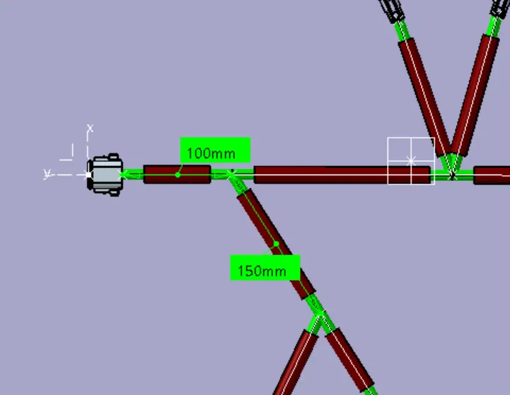
- Click on MULTI-BRANCHABLE DOCUMENT, give the branch diameter and bend ratio. Open route definition and click on the connector then a wire will be created automatically between the connector.
- To give the routing from the main branch use ADD BRANCH POINT command at the required location and create sub-branches.
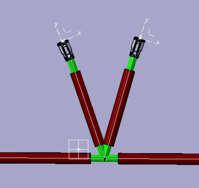
- Now, add corrugated tubes on a wire for protection purposes by using the LIGHT PROTECTION COVERING command. Select corrugated tube from cot_tube catalog.
- Cover all the branches with a corrugated tube, given the extremity point is taking 20mm.
Wire harness assembly:-
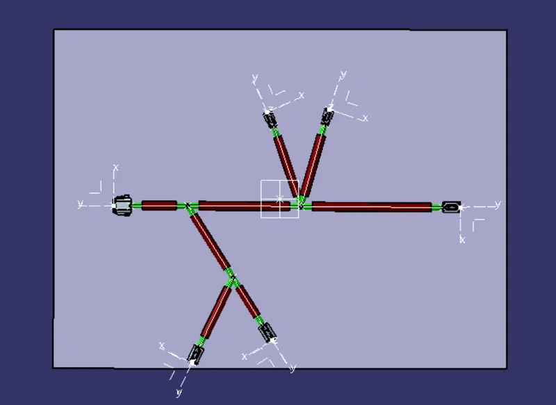
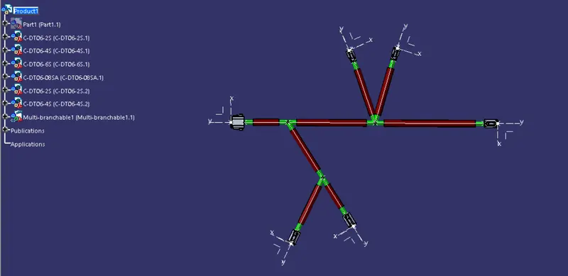
Conclusion:-
- Wire harness developed in CATIA V5.