Wiring harness design in CATIA V5 - 3D modeling Week 4 Challenge
Wiring harness design in CATIA V5 - 3D modelling : Week 4 Challenge
AIM
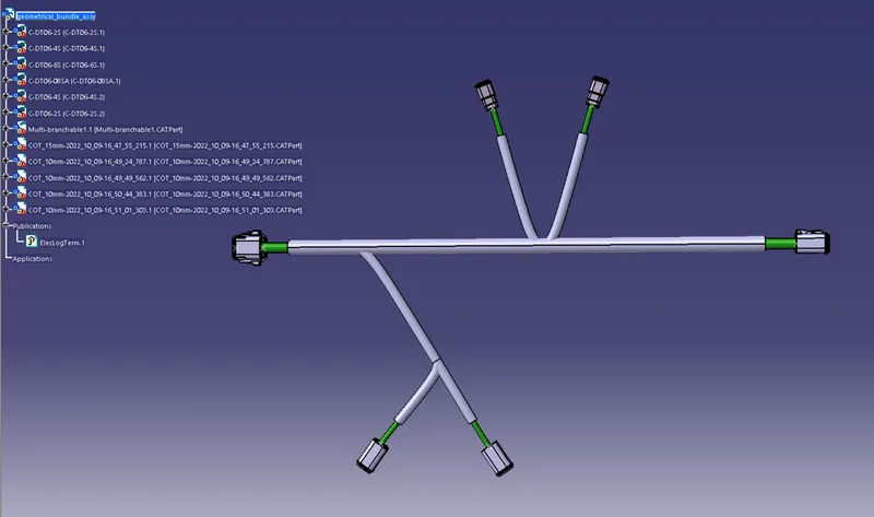
Route the following harness layout in Electrical workbench. Make assumption for harness bundle diameters. Use Following connectors as shown in layout diagram.
Download connector 3D data from www.te.com
DT06-4S
DT06-6S
DT06-2S
DT06-08SA
INTRODUCTION :
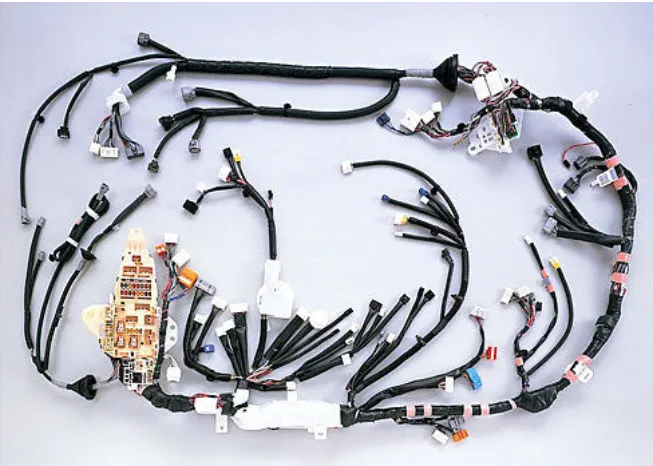
Wire harness connectors and terminals are basic components found in a wire harness. A wire harness, sometimes referred to as a wire assembly, is a set of multiple wires or cables in their own protective covers or jackets that are bundled into a single wire harness. Wire harnesses keep electronic or electrical systems organized to transmit signals, relay information, or electrical power.
Automobile wiring harness is the main part of automobile circuit network. As people on car safety, comfort, economy and emission requirement, car appliances configuration, function more and more, so a connect the electrical wiring harness is becoming more and more complex, become a link with contemporary car trouble, and therefore in car design and manufacturing is more and more attention. How to improve the comprehensive performance of automobile wiring harness has become the focus of attention.
The function of wire harness in the whole vehicle is to transmit or exchange the power signal or data signal of the electrical system to realize the functions and requirements of the electrical system.
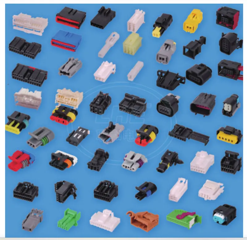
Connectors are the electro-mechanical devices used to form a continuous electronic signal to connect wire harnesses to a power source or circuit. On a basic level, connectors consist of male-ended plugs and female-ended jacks that can be joined together to relay an electronic signal. They are the familiar mating pair of polarized multi-pin connectors with wire leads. A male-ended plastic housing with release fits into a snap-mounted female-ended chassis mounting. The pair can be connected or disconnected easily and come in a variety of sizes, shapes, materials, quality, and dimensions—circular, header, pin, crimped, multitap—which are dependent on the application.
OBJECTIVE
- Define the Mechanical connectors electrically and store it in the Catalogue.
- Prepare the bundle routing for the connectors and orient the bundle in proper direction using rotate command
- Add the protective coverings to the bundles created, where 30mm gap should be provided at start and end extrimities near to the connectors
DESIGN PROCEDURE
1.Procedure of the connector for defining it electrically.
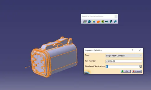
Download the required Connectors from the source and convert the mechanical connectors electrically by using the electrical part design work bench by following below steps.
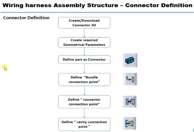
- First download the connectors and mounting clip from the given link source.
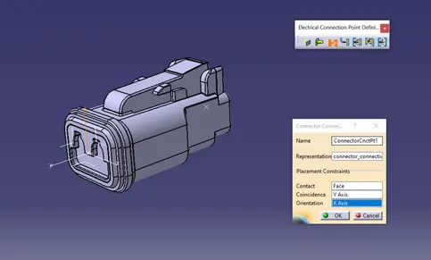
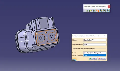
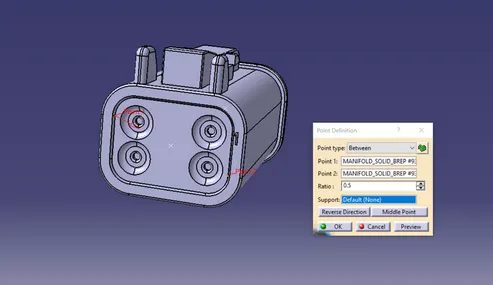
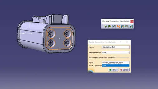
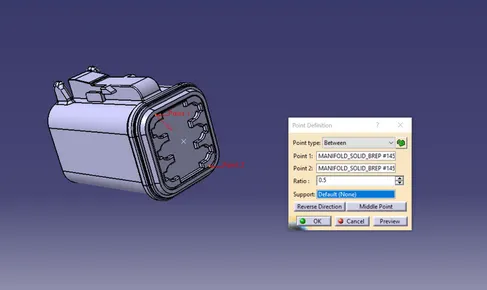
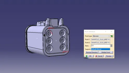
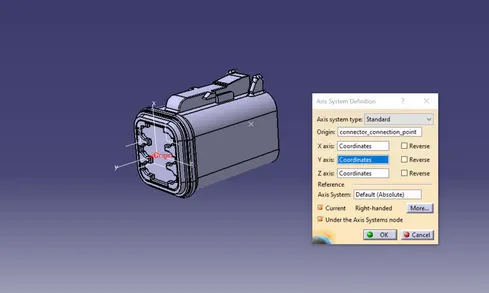
- Get into the mechanical part workbench to create required geometrical parameters. Create connector connection point and bundle connection point on the required sides of the CAD part.
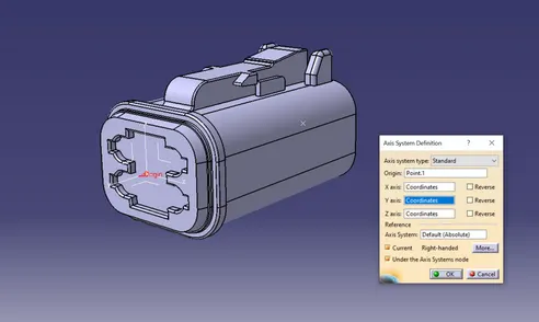
- Create axis system on the connector connection point such a way that the Y coordinate facing normal to the connector face, X coordinate facing towards the locking mechanism and Z coordinate facing to the top.
- Create cavity connection point for connectors having the cavity for mounting clips
Using the geometrical parameters created,
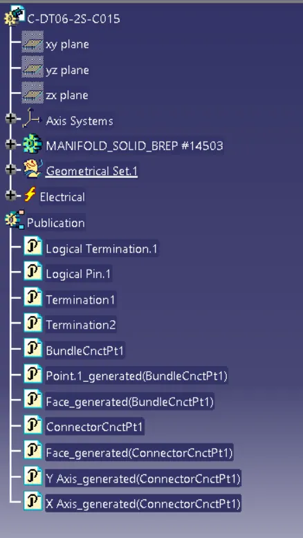
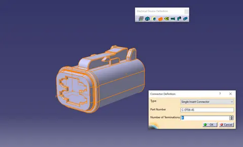
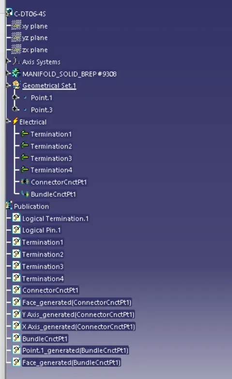
- Define part as electrical connector.
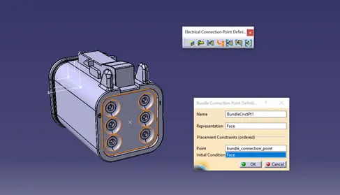
- Define bundle connection point.
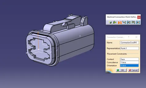
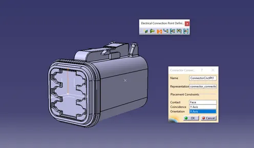
- Define connector connection point.
- Define cavity connection point.
DT06-2S :
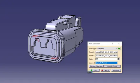
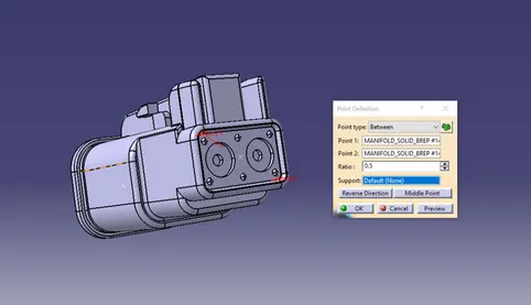
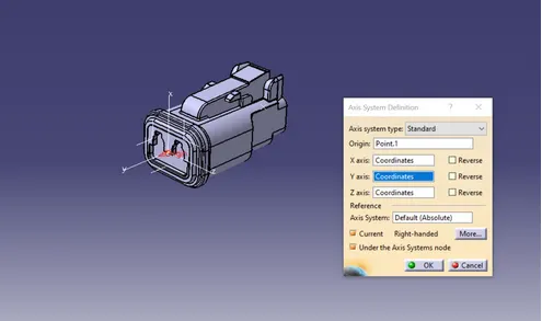
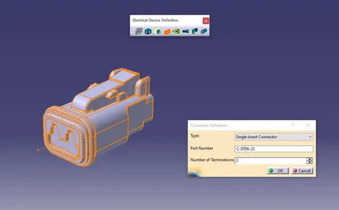
DT06-4S :
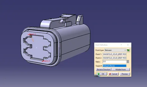
DT06-6S :
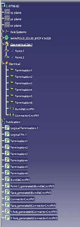
DT06-08SA :
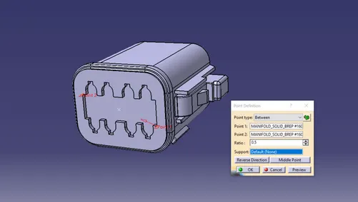
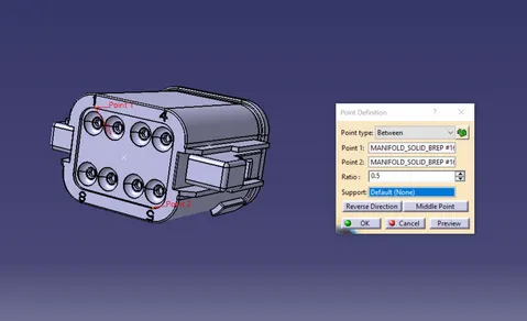
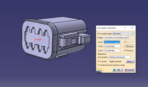
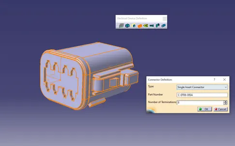
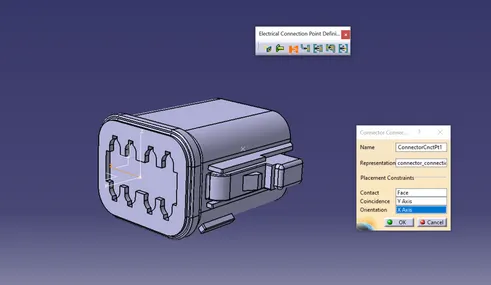
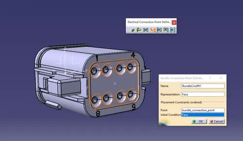
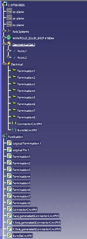
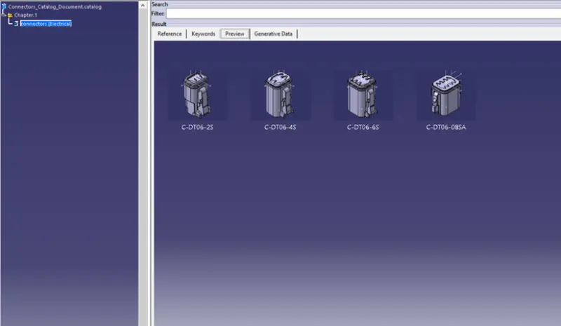
- Add all the Electrically defined connectors to the Connectors catalogue documents :
Assembly Workbench :
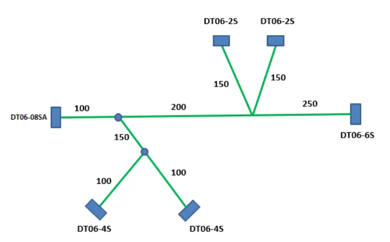
Input diagram for proper alignment of connectors in the wiring harness assembly is given below :

- Using manipulate and snap features move the connectors to the desired positions :

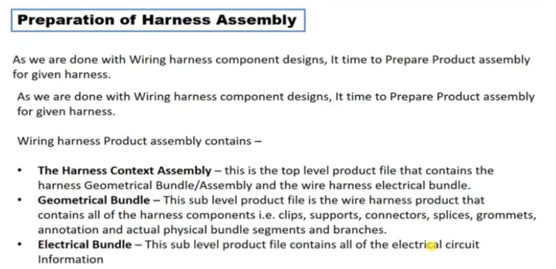
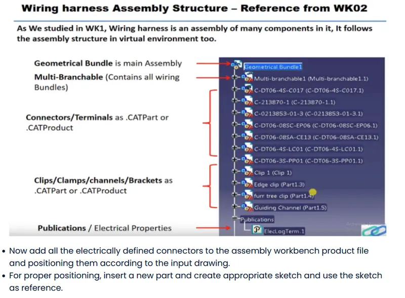
- Then in the Wiring Harness Assembly workbench we need to select the geometrical bundle command and define the product electrically.

- Create main wiring harness bundle using the multi branchable option .
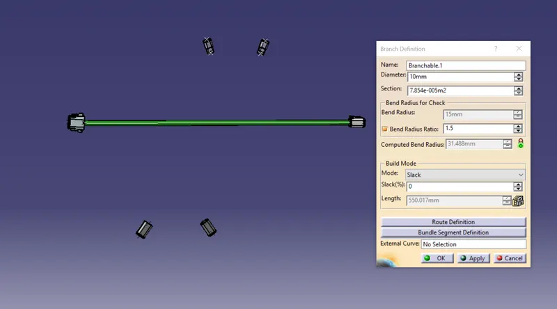
- Create branch points at required spots for sub bundle segments.
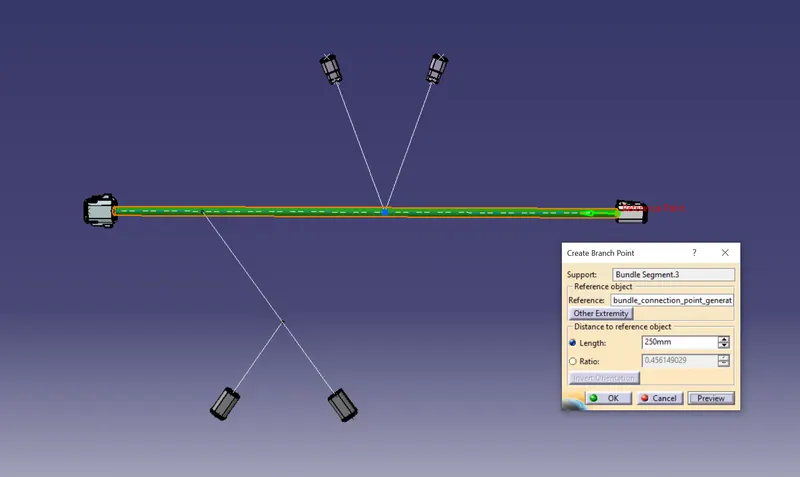
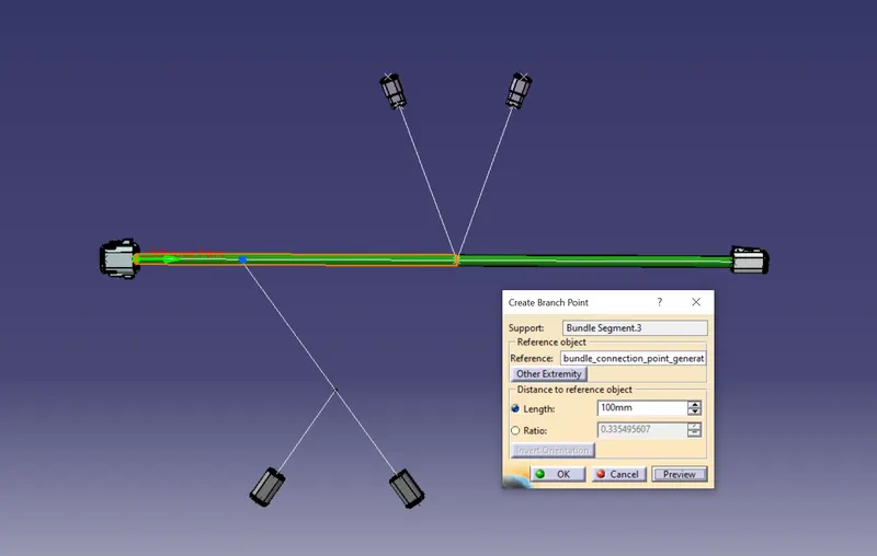
- Now we can add the sub branch in the main trunk (branch).
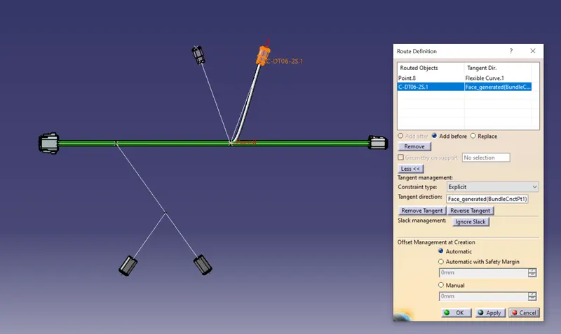
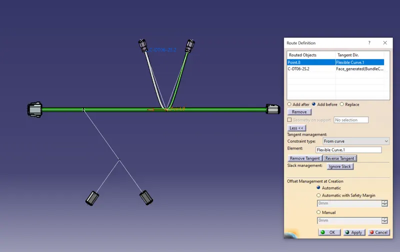
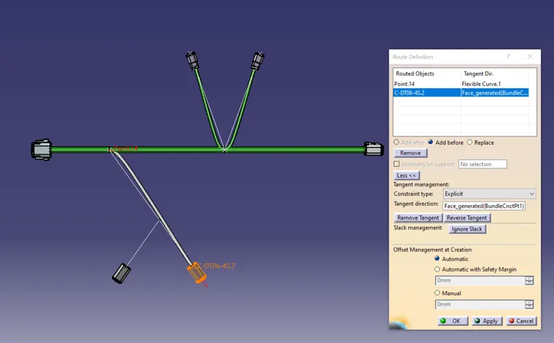
After creating the branches between the connectors, we can add the required protective coverings on to the electrical harness assembly.
COT tubes are already added to the Catalogue.
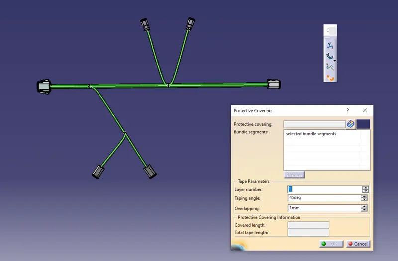
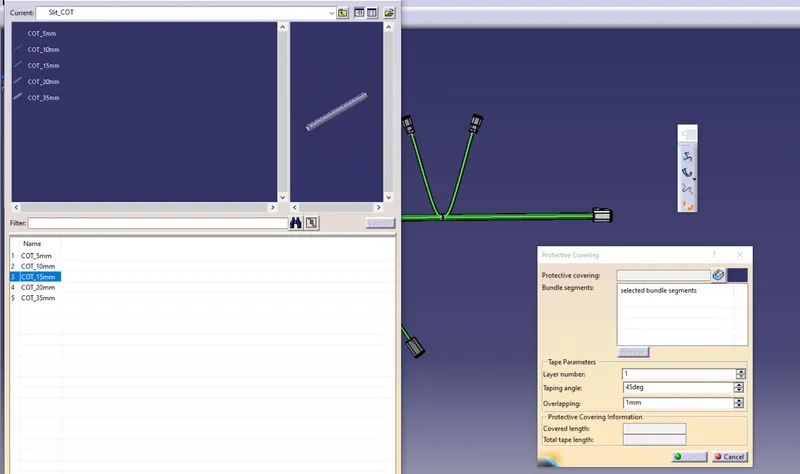
Final Assembly :