Wiring harness design in CATIA V5 - 3D modeling Week 4 Challenge
Wiring harness design in CATIA V5 - 3D modeling
AIM :
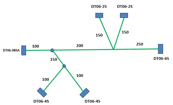
Route the following harness layout in Electrical workbench. Make assumption for harness bundle diameters. Use Following connectors as shown in layout diagram.
Add protective covering on all branches connected to DT06-2S & DT06-4S connectors. Keep end extremity at 30mm (from connectors end)
Download connector 3D data from www.te.com
- DT06-4S
- DT06-6S
- DT06-2S
- DT06-08SA
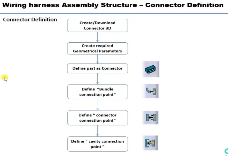
DEFINIG ELECTRIC PARAMETER FLOW CHART
Routing Procedure :
- First download the given CAD data.
- Define it as electical connector or cavity depending upon how the component is going to work.
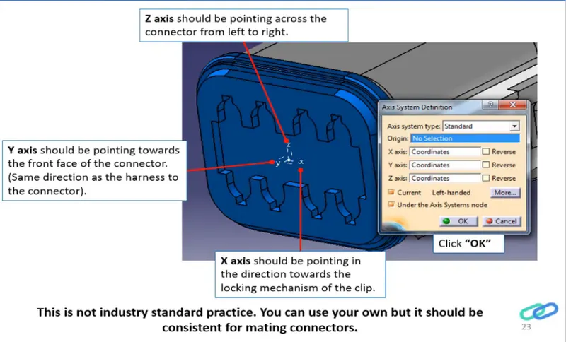
- Then create a mounting point on the connector and create axis system on the point.
- Make sure that the direction of the axis system should be lie according to the conectors.
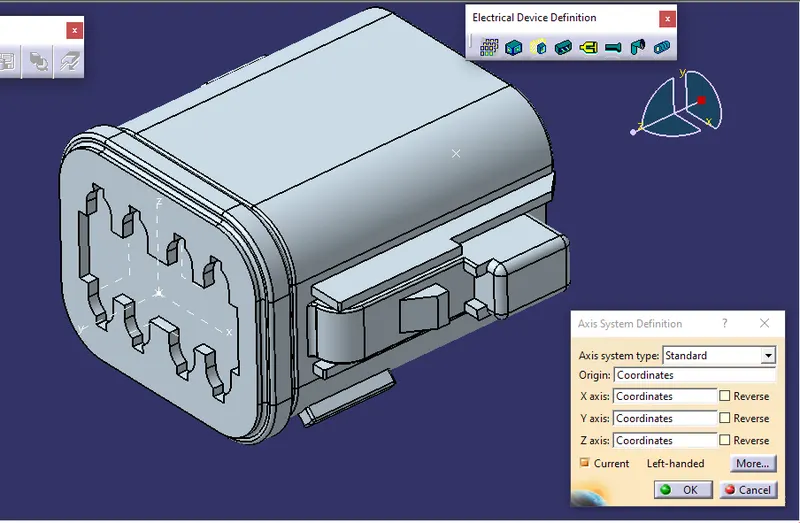
- Here X is point toward the left because the locking mechanism is in the sides of the connector and Y should point the direction from where the bundle and mating part is going to connect. According to the X and Y we can direct the Z.
CONNECTOR DEFINATIONS IN CATIA V5
1. Deutsch DT06 – 08SA
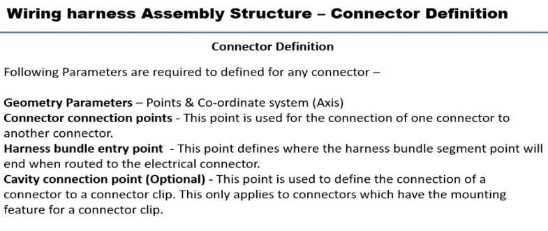
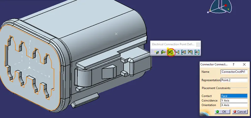
Connector connection point:
Create midpoint on the contact face which will be normal to wire bunddle insertion.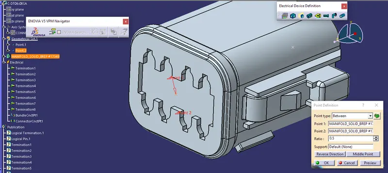
Craete Axis System with respect to the point which we have created and defining the axis direction as shown below,
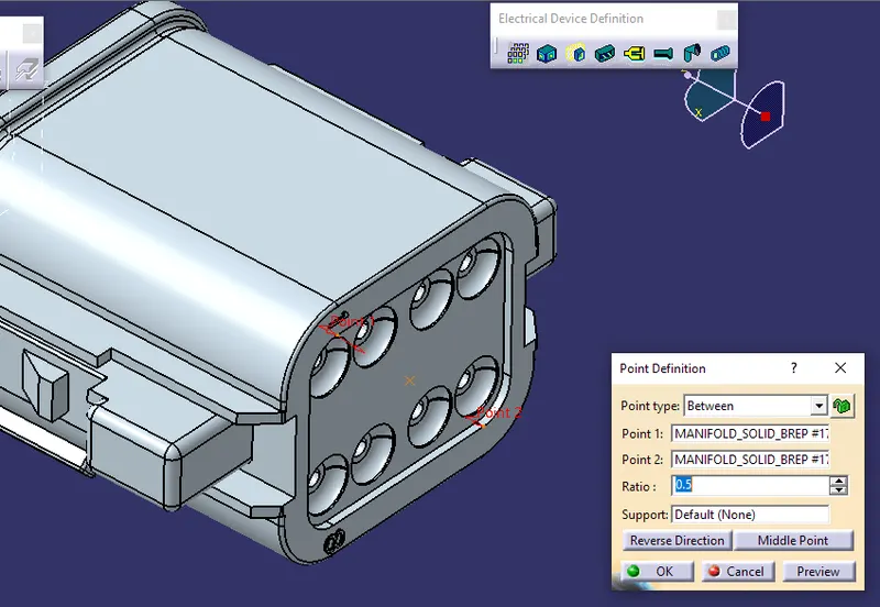
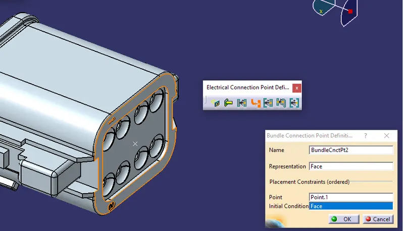
Bundle connection point:
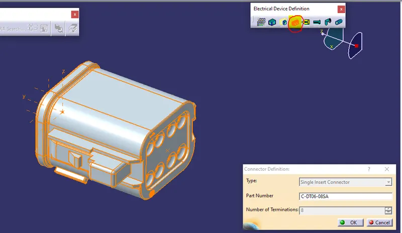
Switch to 'Electric Part Design'
Define the part as connector in catia, give no. of termination as 8 because we have 8 entry points for wire.
Define Bundle connection point
Define connector connection point
So like wise we need to define all the connector as electricaly.
Then open the cad file in catia part design workbench and create the connector connection point,connector connection axis system , bundle connection point .Switch to electrical part design and define it as a connector also define connector connection point and bundle connection point.
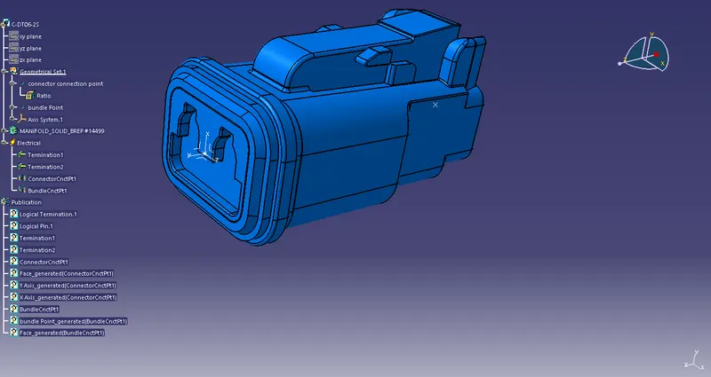
fig.1. Connector DT06-2S
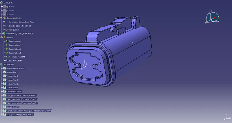
fig.2. Connector DT06-4S
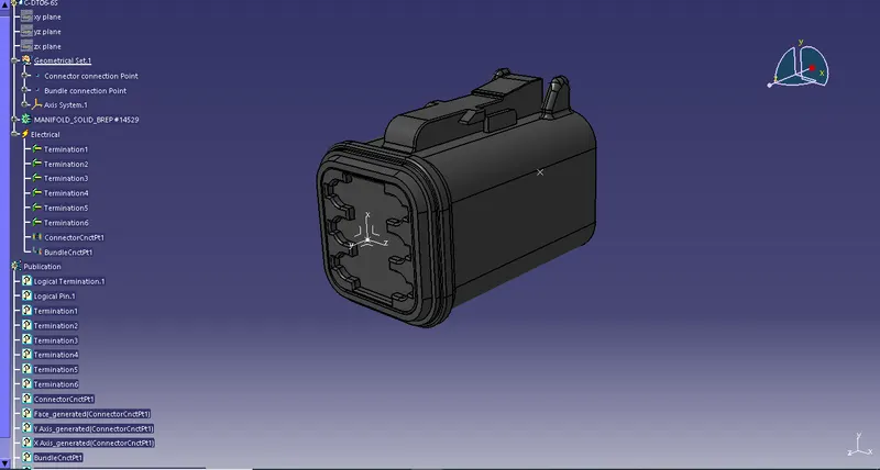
fig.3. Connector DT06-6S
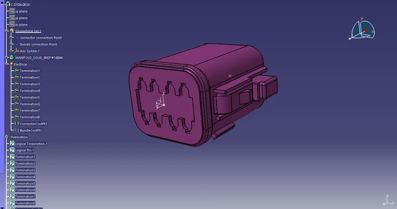
fig.4. Connector DT06-08SA
All the connectors defined as electrical connector and defined all the necessary properties to Connectors.
create a catalog document in connector family and store all the connector data in catalog document .
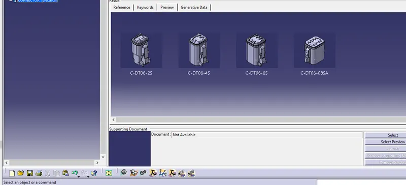
fig.4.Catalogdocument
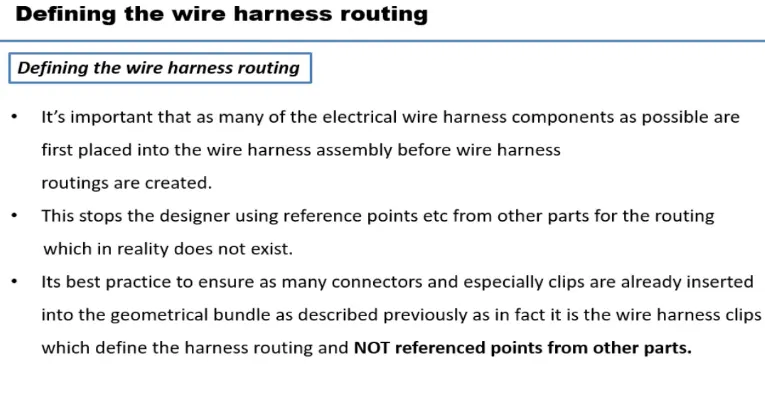
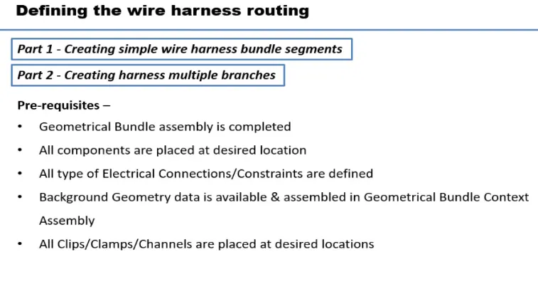
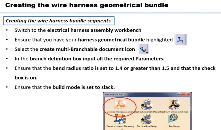
Click on Branch defination
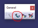
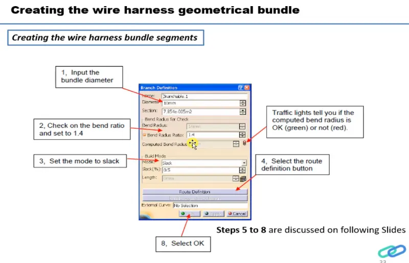
Then click on route defination
select connectors in between we want to create branch.
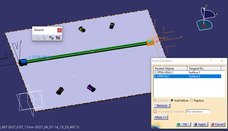
TO add branch point
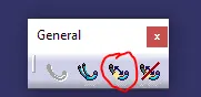
select the branch then give ratio or dimension for the point
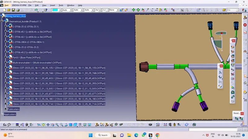
Final wire harness routing
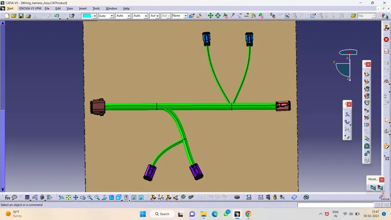
Now to create protective covering on all branches
switch to electrical harness assembly
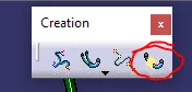
select protective covering then select branch - select catalog - select approprite slit cot tubes - give extrimity at start and end - ok
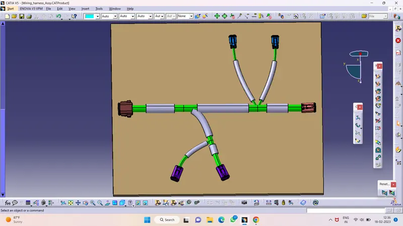
Tree Structure :