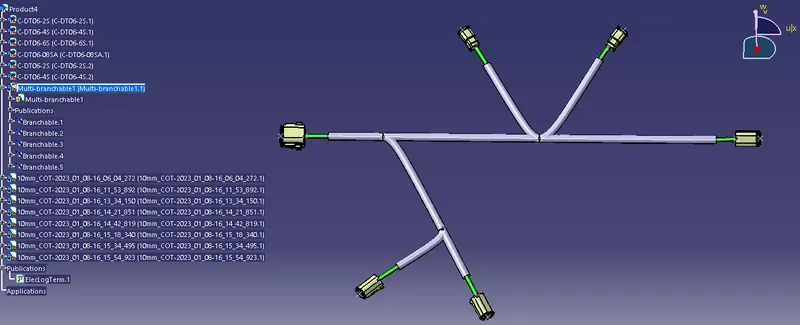
Wiring harness design in CATIA V5 - 3D modeling Week 4 Challenge
Wiring harness design in CATIA V5 - 3D modeling Week 4 Challenge
Aim:-
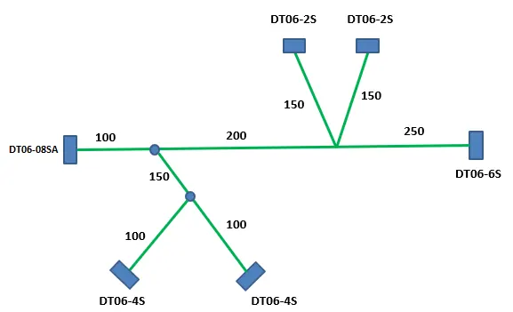
Q1. Route the following harness layout in the Electrical workbench. Assume harness bundle diameters. Use the following connectors as shown in the layout diagram. Add protective covering on all branches connected to DT06-2S & DT06-4S connectors. Keep end extremity at 30mm (from connectors end)
Download connector 3D data from www.te.com
- DT06-4S
- DT06-6S
- DT06-2S
- DT06-08SA
Solution:-
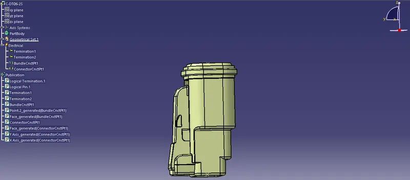
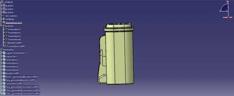
Initially, all the connectors are electrically defined using the below steps -
- Download Connector 3D
Mechanical Part Design
- Defining Geometrical Parameters (Points and Axis system)
Electrical Part Design
- Define part as Connector
- Define Bundle Connection Point
- Define Connector Connection Point
The catalog is also been created for all the electrical connectors to use in the Geometrical bundle using Catalog Browser.
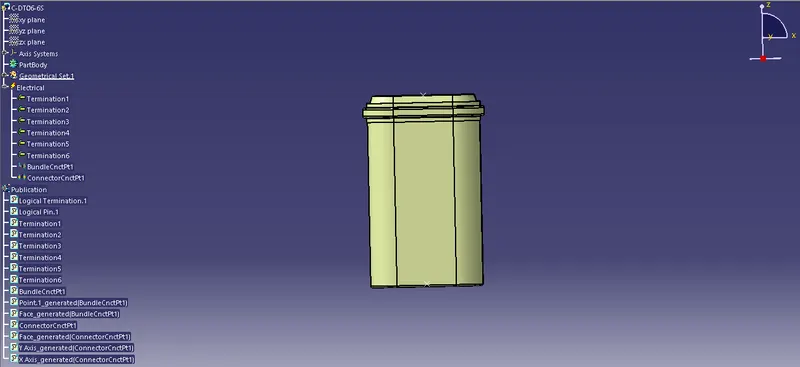
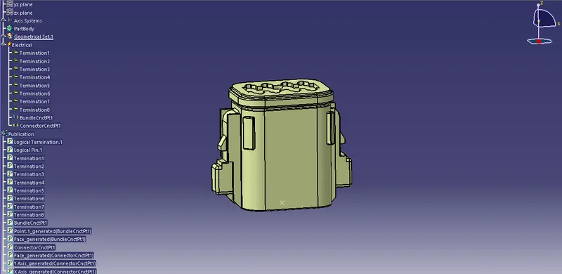
Harness Context Assembly
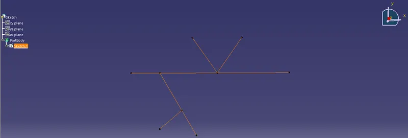
Sketch and Geometrical Bundle are the components of the harness context assembly.
Sketcher (Mechanical Design)
- Line
A sketch is created for the harness context assembly from Sketcher. Line command is used to create the sketch with the required parameters.
Geometrical Bundle Assembly
Mechanical Assembly Design
- Catalog Browser
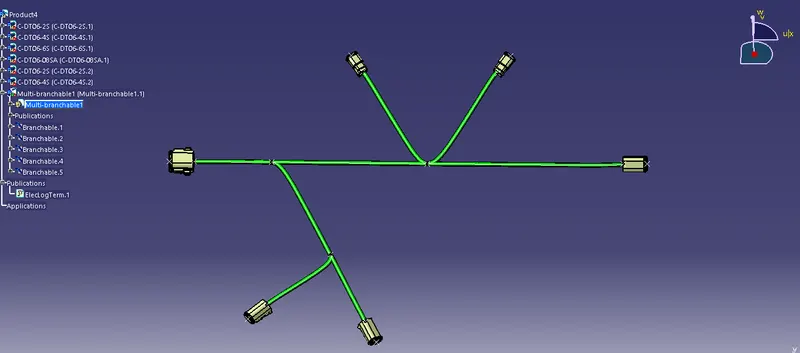
All the electrical connectors are loaded in the geometrical bundle using Catalog Browser from their catalog. Manipulation, Snap, and Compass are the tools used from the mechanical assembly design workbench to place the connectors at the desired positions of the sketch.
Electrical Harness Assembly
- Geometric Bundle
The geometric Bundle command is used to electrify the geometrical bundle.
- Multi-Branchable Document
The multi-Branchable Document command is used to initiate branches for the electrical components using Branch Definition.
Electrical Harness Installation
- Branch Definition
Branch Definition command is used to define the branches between the components. Branch diameter (5mm), Bend Radius (ratio 1.4), and Build Mode is set in the branch definition before proceeding with the Route Definition.
In Route Definition, objects/components are selected for which the branches are to be made.
- Add Branch Point
Branch points are created from the main branch using Add Branch Point command. The branch is selected for which the branch point is to be created and distance is defined for the branch point. New branches can be created through the same branch point.
- Protective Covering
Protective covering (COT Tubes) on all branches are connected with the end extremity of 30mm (from the end of the connector). Bundle segments are selected then the protective coverings are implemented using a catalog.