Wiring harness design in CATIA V5 - 3D modeling Week 4 Challenge
WIRING HARNESS DESIGN 4
AIM:
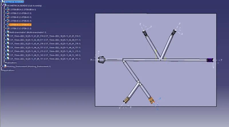
To create wire routing between the above mentioned connectors by referring the below layout diagram.
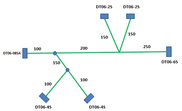
OBJECTIVE:
To download the 3-D CAD part of the below mentioned connectors from the maker's website.
The connectors to be used in the wire harness routing are:
DT06-4S
DT06-6S
DT06-2S
DT06-08SA
Define the Electrical properties of all the connectors.
Create the wire harness layout by referring the above layout.
To add protective covering on all branches connected to DT06-2S & DT06-4S connectors and keep end extremity at 30mm.
SOLUTION METHODOLOGY:
Step - 1:
Download all the 3-D CAD parts from the manufacturer's website.
Open all the 3-D CAD parts in the CATIA V5 software and save it in the desired folder.
Step - 2:
Identify the Bundle side and Connector side.
Navigate to the Part Workbench and create mid-points at the Bundle side and the Connector side.
Create an Axis system at the Connector side by keeping:
Y-axis: Normal to the mating surface
X-axis: Normal to the locking surface
Step - 3:
Navigate to the Electrical Part design workbench and define the parts as a Connector.
After that define its Electrical properties by defining the Connector connection point and Bundle connection point.
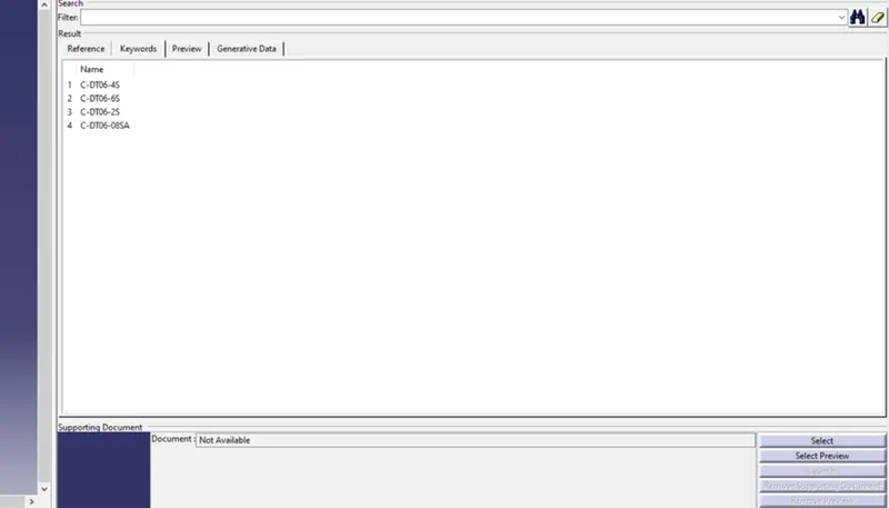
After defining the Electrical properties save the files in the same folder and also add the components to the catalogue document to the connectors family so that it can be used later.
DT06 - 2S:
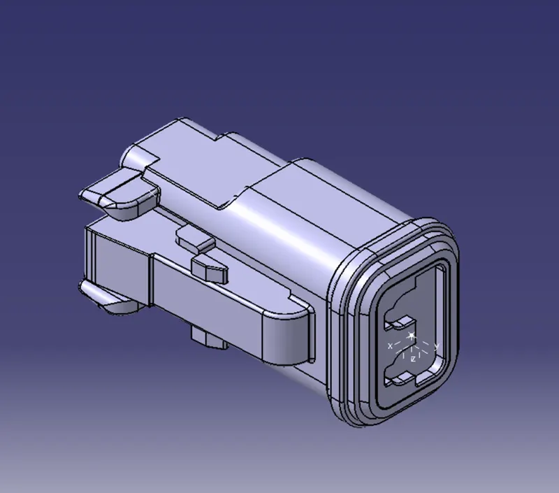
DT06 - 4S:
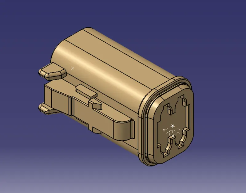
DT06 - 6S:
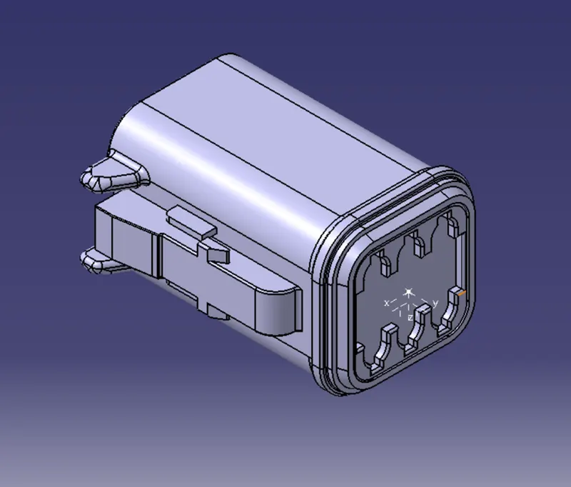
DT06 - 08SA:
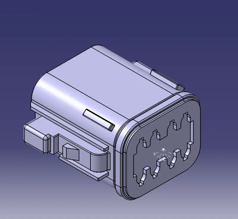
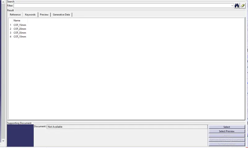
Catalogue Document:
Step - 4:
Create a Product and name it as required.
Step - 5:
Create another product inside the main product which will be the 'Geometry Bundle' assembly file which will contain all the connectors and the wire harness routing will be done inside the Geometry Bundle.
Step - 6:
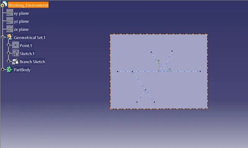
Create a new part as the 'Working Environment' and insert the part in the main assembly using Existing component command.
WORKING ENVIRONMENT:
Step - 7:
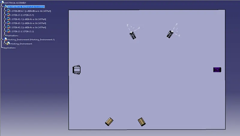
Now we need to navigate inside the Geometry Bundle assembly and add all the connectors mentioned above by using the Existing component command.
Step - 8:
Now position all the components according to the given layout to start routing the wire bundle.
Step - 9:
Now navigate to the Electrical Harness Assembly.
Inside the Electrical Harness Assembly select the Geometry Bundle command and then click on the Geometry Bundle Assembly or Product.
Step - 10:
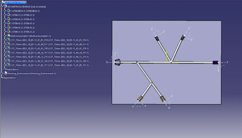
After creating the Geometry Bundle, we have to select the Multi branchable document command and start routing the wire bundle as displayed in the reference diagram.
Step - 11:
Apply the protective covering on all branches.
The protective coverings applied are the Corrugated tubes that are created previously and was stored in the catalogue documents.
According to the diameter of the wire bundle respective corrugated tubes are inserted from the catalogue.