Week 8 - Challenge 1 - Base Bracket Design
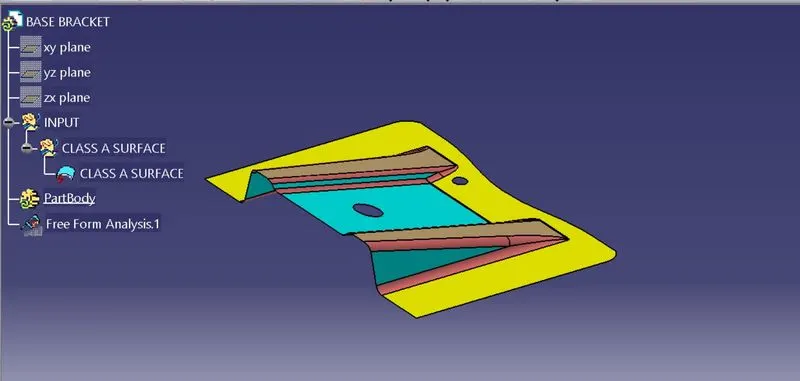
OBJECTIVE :- Create the Base Bracket Plastic component through the given Class-A surface. To begin with, the tooling axis for the given Class-A Surface should be created meeting the requirements of the draft angle and at the end perform the Draft analysis on the model.
Step of Draft Analysis :
- enter SURFACE in Catia V5.
- Go to Material Mode.
- go for draft analysis.
- drag axis bar to the tooling direction of part.
- Check for draft and make parting line as per analysis
Draft Analysis:
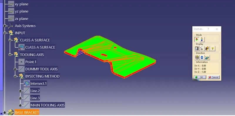
With draft analysis, verify draft angles, examine angle changes within a face, as well as locate parting lines, injection, and ejection surfaces in parts.
PROCEDURE FOR CREATING TOOLING AXIS
- First, the given styling surface was imported into CATIA and checked for irregularities by using Join, Boundary and Disassemble option.
- By using the boundary option the boundary of the hole was created and the centre point was marked.
- Then a dummy tooling axis was created with the centre point in the z-direction.
- By using the axis system the intersection curves were created over the xz plane and then the sides were extended by using point to point line then by using bisecting lines the tooling axis in X direction was created.
- Then by using zy plane the intersection curves were created as shown below and the same procedure was followed for creating the tooling axis in the Y direction.
- Bisecting lines were used to get the exact medium from the two sides so that maximum positive draft angle can be achieved.
- Finally by using the bisecting line option the tooling axis were created by selecting the tooling axis x direction and y direction axis.
GREEN COLOR:- 3 DEGREE
BLUE COLOR:- LESS THAN 3 DEGREE
RED COLOR:- NEGATIVE DEGREE
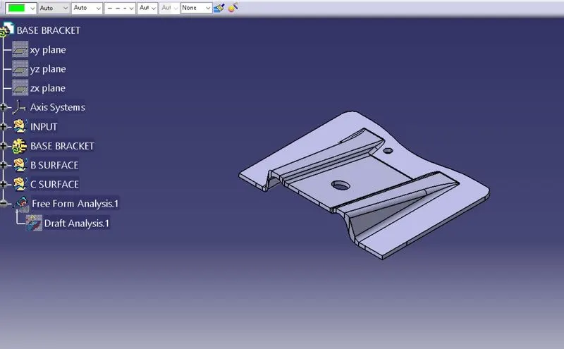
ISOMETRIC VIEW
TOP VIEW
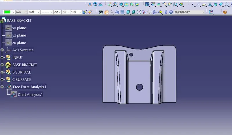
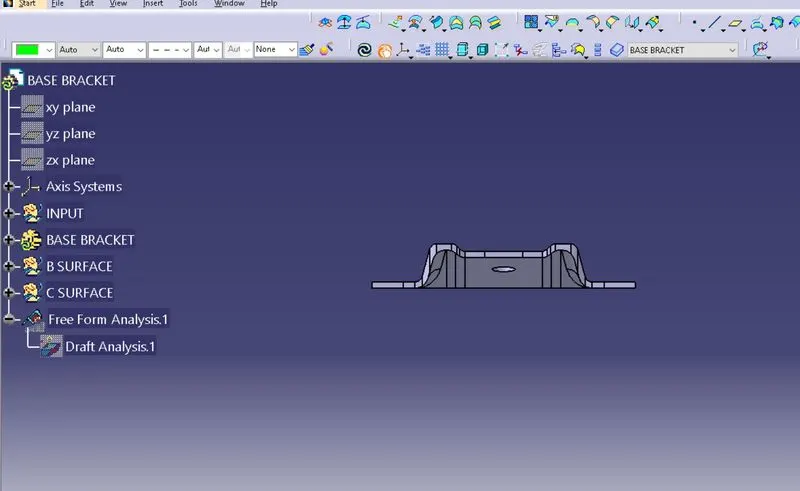
FRONT VIEW