Wiring harness design in CATIA V5 - 3D modeling Week 4 Challenge
- Wiring Harness Routing of given data in Electrical Workbench :
- For this we need all given Connectors, so we have to first download it from internet open source.
- We have to download following Connectors :
- DT06-4S
- DT06-6S
- DT06-2S
- DT06-08SA
- Once we get all above Connectors, then we have to give Points and Axis at Connector mating faces and Points at Bunddle entry sides in Mechanical Part Workbench separately for each Connector.
- Then we have to shift into Electrical Part Workbench, in this workbench we have to define Connector, Connector Connection Point, Bunddle Connection Point by using respective tools. In this way all Connector will be define as Electrical part.
- Now we can add this Connectors in Catalog file.
- As above all things we have done, then we have to open New Product file, give name as Wiring Harness Context Assembly and open new product in it, name as Geometrical Bunddle Assembly.
- In Geometrical Bunddle, all required Connectors we have to add from Catalog file.
- We have to give position and distance to all Connectors as per given in layout.
- For that we can use Manipulation, Translation or Rotation, Compass tools for translate or rotate the Connectors at respective positions in Mechanical Assembly Workbench.
- Once all Connectors Placed on their respective positions, now we can shift to Electrical Harness Assembly Workbench.
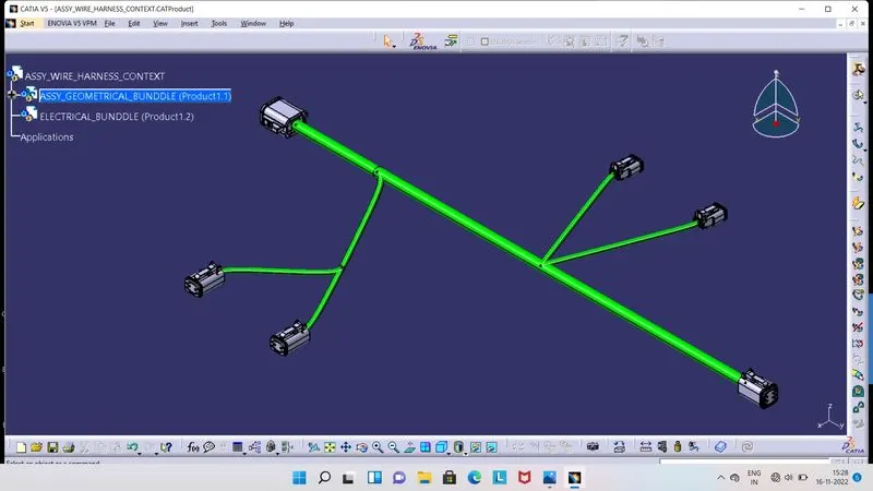
- As we entered inside the Electrical Harness Assembly Workbench, we have to click on 'Geometrical Bunddle' tool and then on ASSY_GEOMETRICAL_ BUNDDLE. So we can see that, icon of that particular product will get change.
- Now we have to route the bunddle between placed Connectors, so click on 'Multi-Branchable Document' tool. So Wire Harness Installation Workbench will get open, here we can now able route the bunddle.
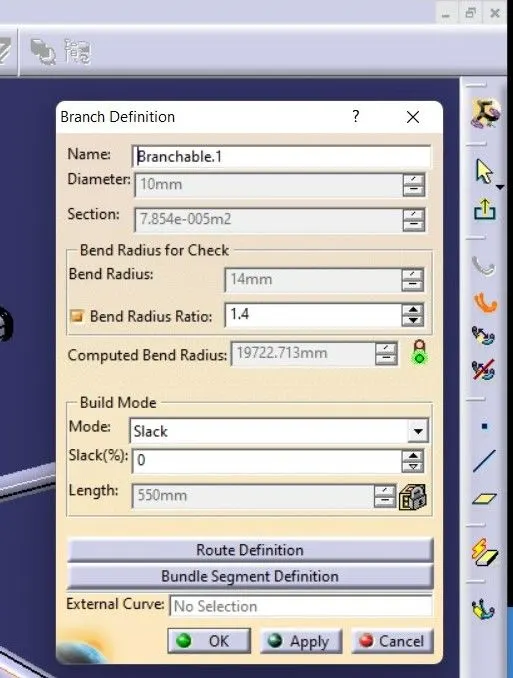
- A box will get appear on screen as shown in above image, in which we have to give the values for Diameter, Bend Radius Ratio and Slack as per requirement.
- Here for above in 1st image, we have given 10mm diameter for middle bunddle and 5mm diameter for its branch bunddles and Bend Radius Ratio is 1.4, Slack(%) is 0.
- Then we have to click on Route Definition.
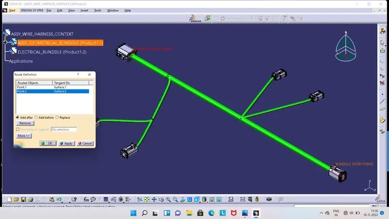
- As we click on Route Definition, a box will get appear on screen as shown in above image.
- In this box, we have to click on those Connectors, at we desire for bunddle.
- So, here we have first click on between two Connectors as shown in image.Then click on Ok, so bunddle will get created between those Connectors.
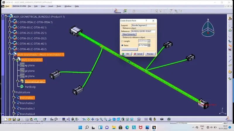
- Similarly, for creating branches of bunddle at right and left side of centered bunddle, we need to split the centered bunndle from given point.
- For that, we have click on 'Create Branch Point' tool.
- So a box will get appear on screen as shown in above image, in which we have to give reference and point at where we want to split the bunddle.
- In this way we can create branches of bunddle.
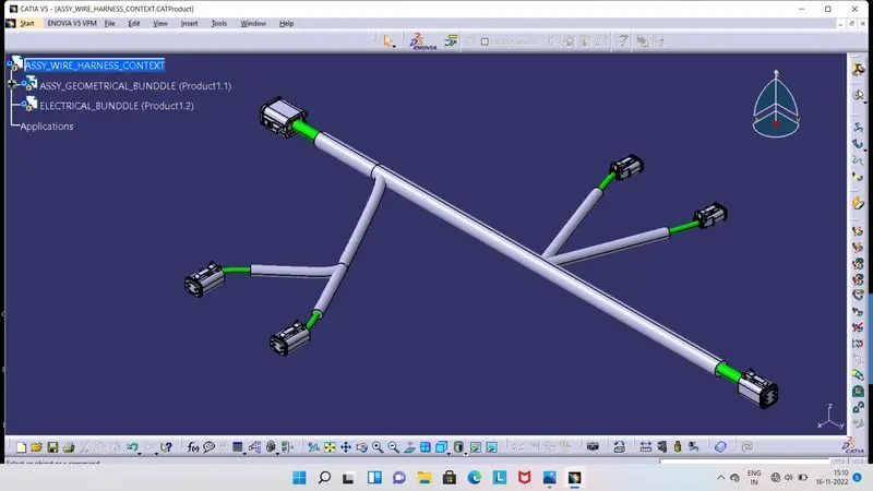
- Once buddle are created between all Connectors, so for protection of bunddle from surrounding environment effects and for eshthetic appearance, we can apply Protective Covering on the bunddles.
- In above image, we can see that, how Protective Covering is apply on bunddles.
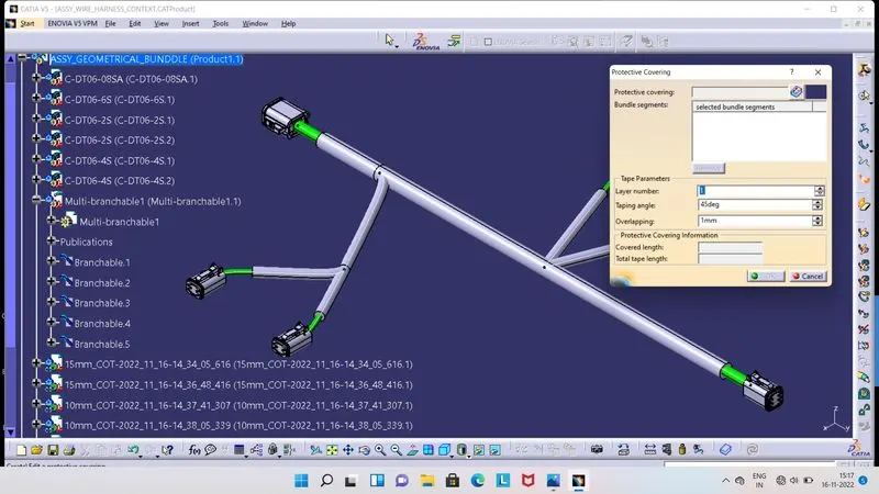
- For apply the Protective Covering on bunddle, we have to shift again in Electrical Harness Assembly by just click on Exit tool or double click on Geometrical Product in tree structure inside the Electrical Harness Installation Workbench.
- We have to keep save the Corrugated tubes of different diameters in Catalog file for our ease. So now we have to click on 'Protective Covering' tool, a box will get appear on screen as shown in above image.
- Here we have select the bunddle first, on which we want Protective Covering, then click on icon of book, from there select the SlitCOT Catalog file, which we have created earlier.
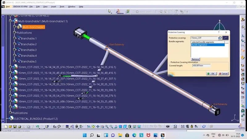
- From that SlitCOT Catalog file, we can select Corrugated tube as per requirement, here we have selected 15mm_COT for 10mm diameter bunddle and 10mm_COT for 5mm diameter bunddle.
- As we select respective dimension COT, it will get applied on selected bunddle.
- In above image, we can see that, there is 'Start Extremity' and 'End Extremity'.
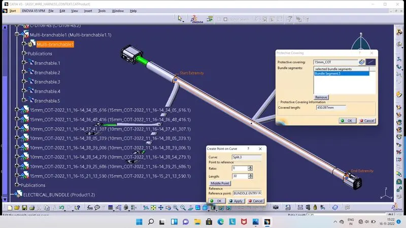
- As we select any respective COT from Catalog file, it will get apply on selected bunddle fully.
- But at the Bunddle Connection Side of Connectors, we will do some work there, so we have to keep some distance of Protective Covering from Bundle Entry Side of the Connectors.
- For keep this distance, double click on End Extremity, so a another box will get appear on screen, as shown in above image.
- In this box at length section, give the distance value as per requirement. We have given 30mm End Extremity.
- Similarly for all bunddles, we have to appply respective diameter Corrugated tube and then 30mm End Extremity, so eventually at all bunddles COT get applied.