Wiring harness design in CATIA V5 - 3D modeling Week 4 Challenge
Wiring harness design in CATIA V5 - 3D modeling Week 4 CHALLENGE
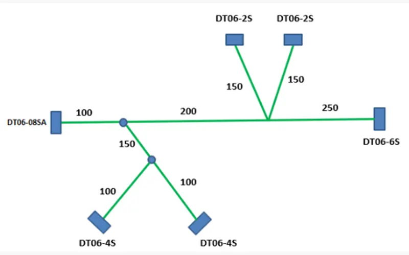
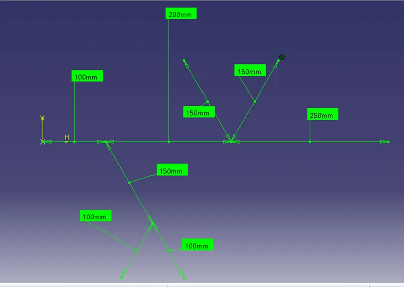
AIM- To Route the following harness layout in the Electrical workbench, according to the diameter provided positioning the connector as per layout. Use the Following connectors as shown in the layout diagram. Add protective covering on all branches connected to DT06-2S & DT06-4S connectors. Keep end extremity at 30mm (from connectors end).
INTRODUCTION-wiring harness routing deals with desired path of wiring harness into given vehicle environment by applying set of design rules &industry best practices. Or in other word A wiring harness routing structure includes a wiring harness routing member configured to be attached to a vehicle body and a protector that accommodates and holds a wiring harness.
DESIGN LAYOUT OF CONNECTOR POSITION
Download connector 3D data from www.te.com
- DT06-4S
- DT06-6S
- DT06-2S
- DT06-08SA
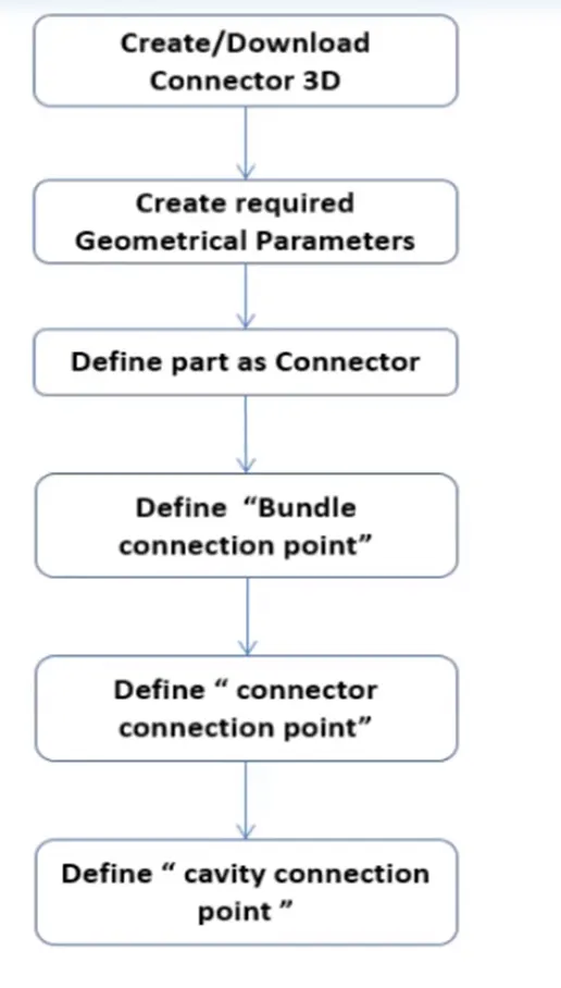
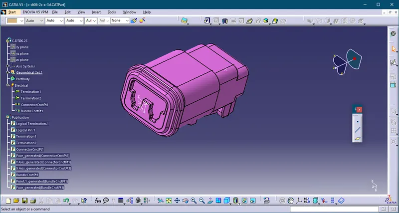
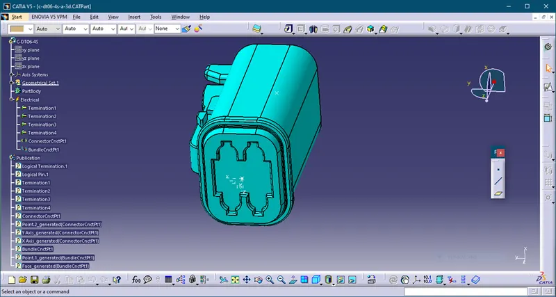
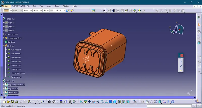
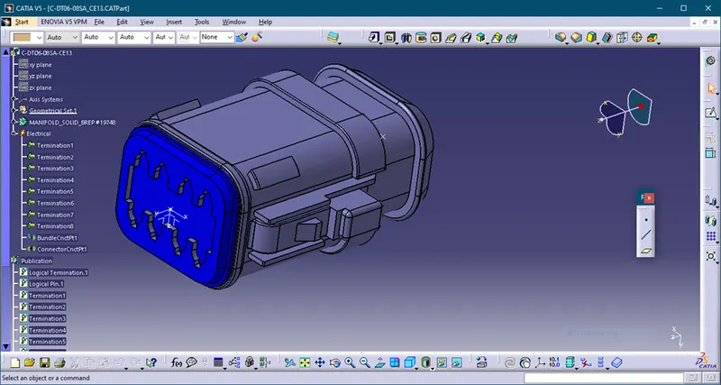
The connector is the mechanical part that need to be converted into electrical part in order to route the harness.
C-DT06-2S
C-DT06-4S
C-DT06-6S
C-DT06-08SA
DESIGN METHODOLOGY-
Create a main product and name it as a context assembly in which create two more product file by the name of geometrical bundle and skeleton part drawing, the skeleton part drawing is used just for the reference of positioning of the connectors they do not have any significance as such in routing. In the geometrical bundle assembly jump to electrical harness assembly workbench and define assembly/product as geometrical bundle.
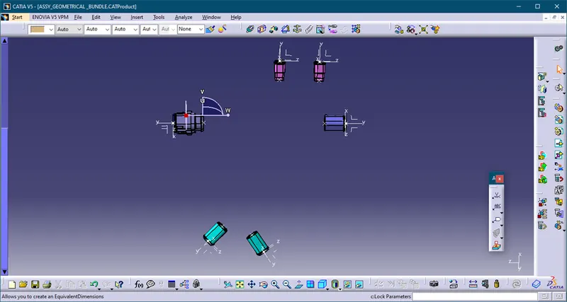
Define all the connectors geometrically in Part Design Workbench. Define all the connectors electrically in Electrical Part Design Workbench. Create a new part document and create the desired routing layout using the line tool. We give the appropriate distance and angles to the lines. Start the Assembly Design Workbench in Catia and place the connectors in their appropriate places according to the given layout also rotate them into proper orientation. Now start the Electrical Harness Assembly Workbench. We convert the mechanical product into an electrical product by selecting the Geometrical Bundle option from the toolbars and then selecting the product name from the feature tree. Then we will create the branches to connect the different connectors with one another by selecting the multi-Branch able Document option from the toolbars and the giving the values of branch diameter, bent radius, and slack0% in the dialog box. After that we will click on the Route Definition option from same dialog box and then select the two connectors between which the branch is to be created. Click ok. We will repeat the same process for all the connectors. We will then add protective covering on all the branches connected to DT06-2S & DT06-4S connectors by selecting the Protective Covering option from the toolbars and then selecting the branch on which we want to add the covering and then browse for the required covering from the catalog browser option and then adding it to the branch. And keep end extrimity as 30 mmClick ok. Save the file.
Arranging the connector following layout
Creating Multi brandable for the connector
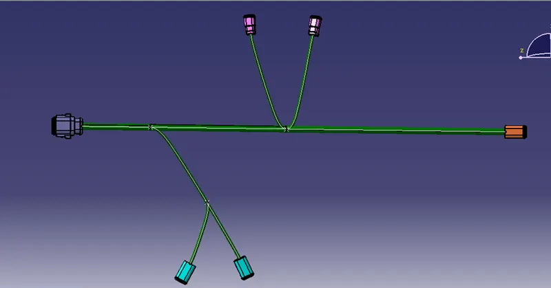
Creating protect covering
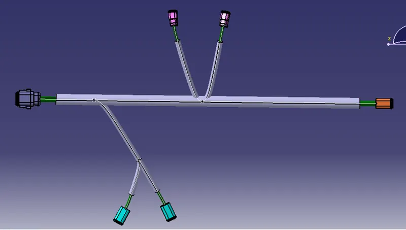
Conclusion- We have learned from this challenge how to open new product and rename it as per requirement and how to arrange as a position as per layout. We also learn multibranch apply and protect covering uses.