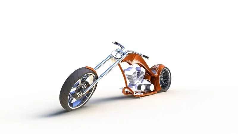
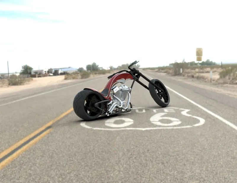
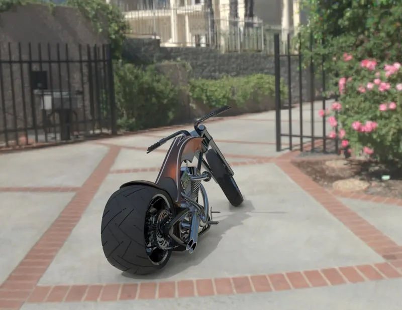
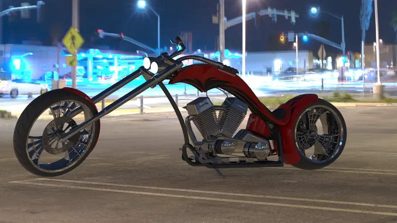
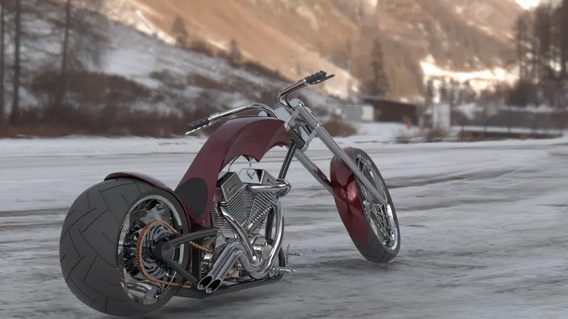
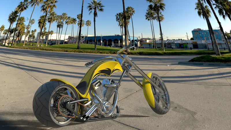
Photo Realistic Rendering
MODELING OF AMERICAN 3D CHOPPER ON SOLIDWORK
ASHIS TARAI
INTRODUCTION:
We are learning in this project making each part of American Chopper Bike on solid works and solid works visualize.
The Different Component Of American Chopper Bike Learning On Solid work;
- Transmission Belt
- Kickstand
- Front Fender
- Rear Fender
- Chain
- Oil Tank
- Pedal
- Front Wheel with Rim, Sprocket, Calipers
- Rear Wheel With Rim ,Sprocket ,Calipers
- Front Fork With Handle Grips
- Chassis
- Engine And Exhaust System
- Gas Tank
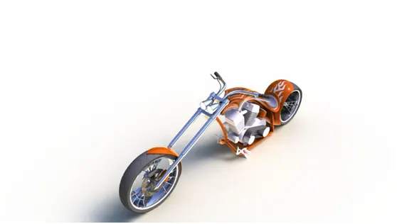
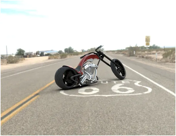
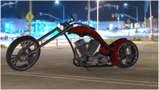
After designing the each part , we have worked upon the assembly and after that the photo rendering of the American chopper which gives it a complete and realistic view.
DESIGN METHODOLOGY:
Starting with the Sketch Of Transmission Belt And After Designing Each Component Through Of Assembly Ending till the Rendering Section .Describe Each Part Step By Step In Flow Chart Below.
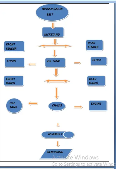
Now we have discuss the all features and properties which are used when designing the model of American chopper Bike. We discuss below attach with image for better understand.
1.EXTRUDE BOSS: Open a new part with model units set to millimeters.
Go to: File > New > Part
Create a 2D sketch
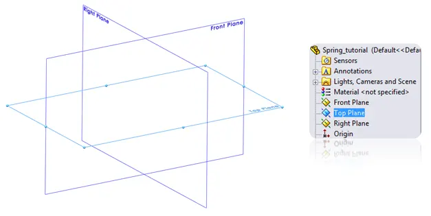
Select the Top Plane in the feature tree (menu at the left side) and create a sketch by clicking on the 2D Sketch icon.
The display changes so the Top plane faces you.
Create a Center Rectangle
Go to Tools > Sketch Entities > Center Rectangle or click on the center rectangle icon
Create a sketch that starts at the Origin.
Change the dimensions of the rectangle to 100 and 150 mm by clicking on the dimension button
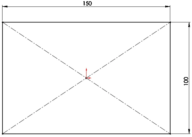
Create an Extruded Boss/Base
Go to: Insert > Boss/Base > Extrude or click on the Extrude icon
The Boss-Extrude menu appears
Direction 1 is set to Blind. When you use the Blind feature you’ll get a solid extrude.
The yellow preview shows the extrusion of the rectangle.
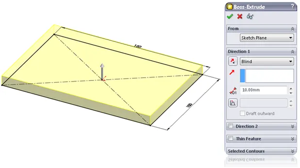
By clicking on the Reverse button you can change the direction of the extrude.
Click a few times at the Reverse button and notice the differences.
With you can change the Depth of the extrude.
Change the Depth of the extrusion to 100 mm.
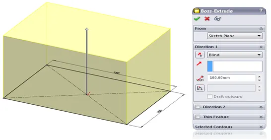
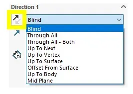
Besides the Blind direction there are a few other Direction Options:
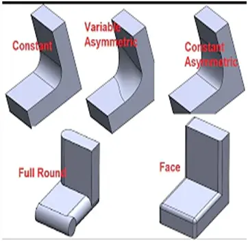
- FILLET: Fillet/Round creates a rounded internal or external face on the part. You can fillet all edges of a face, selected sets of faces, selected edges, or edge loops. There are four types of fillet
1.Constant size fillet 2. Variable size fillet 3. Face fillet 4. Full round fillet
Go to feature then fillet click then show mode type (manual/file expert) fillet type choose any one which is required and then selection window select faces/edges and then fillet radius click ok.
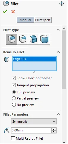
- REVOLVED BOSE FEATURE:
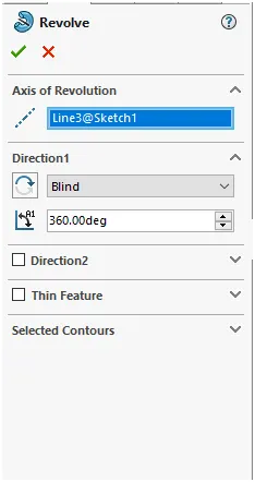
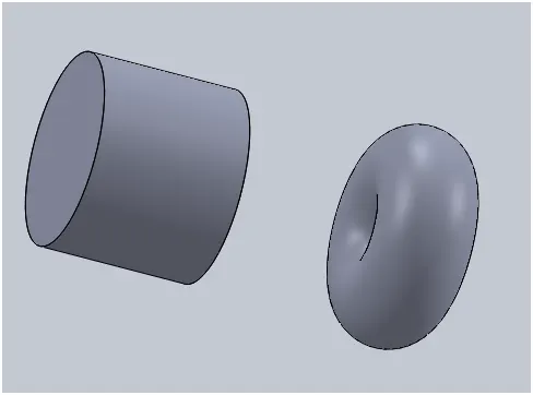
Create a sketch that contains one or more profiles and a centerline, line, or edge to use as the axis around which the feature revolves.
- Click one of the following revolvetools: Revolved Boss/Base (Features toolbar) or Insert > Boss/Base > Revolve. ...
- In the Property Manager, set the options.
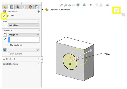
- EXTRUDE CUT: it is similar to boss extrude feature that also need any sketch on solid body which needs to be cut .Under the “From” header there is a drop-down list containing a variety of options of where to start the Cut-Extrude from.
The “From” options are as follows:
- Sketch Plane: The plane in which the sketch was created
- Surface/Face/Plane: A different surface/face/plane than which the sketch was created
- Vertex: A point
- Offset: An offset distance from the original sketch plane.
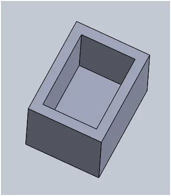
- SHELL: The shell tool hollows out a part, leaves open the faces you select, and creates thin-walled features on the remaining faces. If you do not select any face on the model, you can shell a solid part, creating a closed, hollow model. . You can also shell a model using multiple thicknesses.
To create a shell feature of uniform thickness:
- Click Shell on the Features toolbar or Insert, Features, Shell.
- In the PropertyManager, under Parameters:
- Set Thickness to set the thickness of the faces you keep.
- Select one or more faces in the graphics area for Faces to remove
- Select outward
- Select Show previewto display a preview of the shell feature.
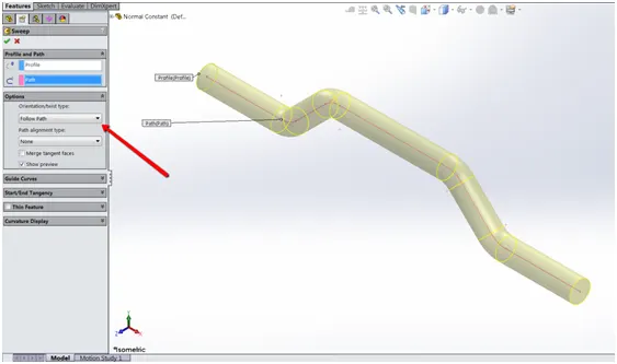
6 . SWEEP BOSE /SWEEP CUT: Adding materials by sweeping shape through a designated path. Applying sweep boss we need to be 2sketch usually in two different planes .sweep cut is opposite to the sweep boss.here we can removing materials by sweeping a shape through a designated path . Set the Property Manager options based on the sweep cut feature. To open this Property Manager: Open a part that has either a closed profile sketch and a sketch path, or a part with a sketch line, edge or curve on the model that you can specify as a path.
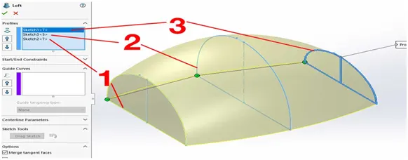
- LOFT BOSS/LOFT CUT: The loft feature is an important tool for (surface) modelling in Solid Works. The loft feature creates a shape by making transitions between multiple profiles and guide curves. This tool is very valuable for modelling complex surfaces loft cut is a solid works features tools which helps to cut or remove material between two or more profile.
.
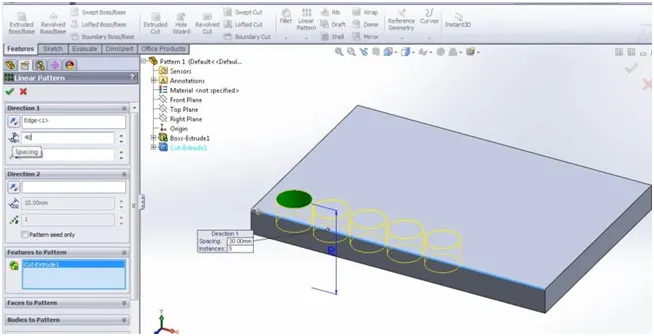
- LINEAR PATTERN: linear patterns to create multiple instances of one or more features that you can space uniformly along one or two linear paths. To create a linear pattern: Create one or more features to replicate. Click Linear Pattern (Features toolbar) or Insert > Pattern/Mirror > Linear Pattern
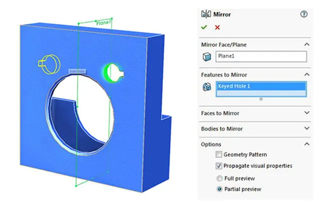
- MIRROR: Creates a copy of a feature, (or multiple features), mirrored about a face or a plane. You can select the feature or you can select the faces that comprise the feature. Bodies to mirror . Select a body in a single model or multibody part to create a mirrorentity.
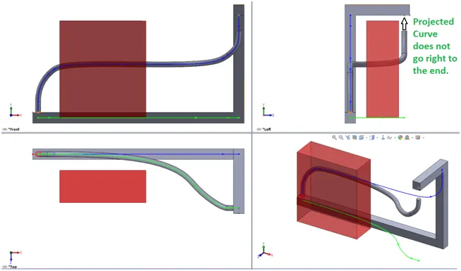
10.PROJECTED CURVE: To project a curve: Click Project Curve on the Curves toolbar, or Insert > Curve > Projected. Under Direction of Projection , select a plane, edge, sketch, or face as the direction of the projected curve. Under Projection Faces , select the cylindrical face on the model where you want to project the sketch. A projected curve is typically used either in sweeps and lofts as path or guide curve. There are two types of projected curves: Sketch on Sketch: Use two sketches to make a single curve. Another is sketch on surface.
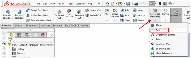
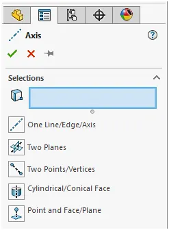
- REFERENCE GEOMATRY: Reference Geometry includes reference planes, axes, coordinate systems, and points. .The Reference Geometry command lives on the Features toolbar, but you can also access it from Insert > Reference Geometry. The Reference Axis Property Manager includes a Selections box where you will define your Reference Axis. The Reference Axis Property Manager includes a Selections box where you will define your Reference Axis. The combinations of these selections that will fully define the Reference Axis are described and depicted below the Selections box.
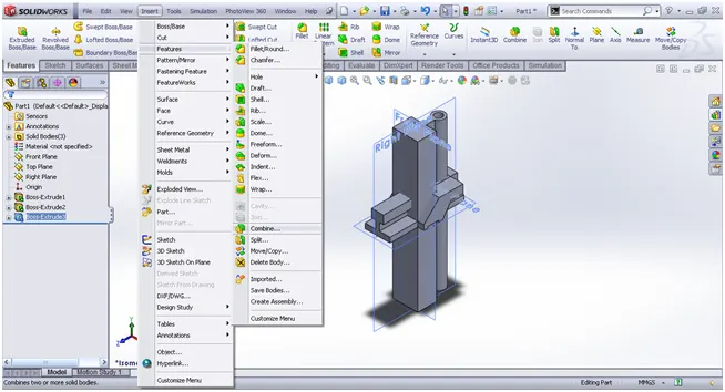
- COMBINE: The Combinefeature lives under Insert>Features>Combine. The common function allows you to add two bodies together, and keep the area that is common to them. To use this feature, we will select the common button, and then under Bodies to Combine, select the two bodies .
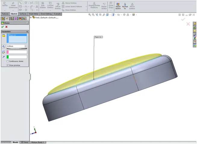
- DOME: The Parameters in the domeProperty Manager include: Faces to Dome. Select one or more planar or non-planar faces. You can apply domesto faces whose centroid lies outside the face. This allows you to apply domes to irregularly shaped contours.
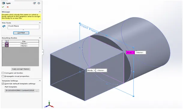
- SPLIT: The SOLIDWORKS SplitLine tool is used to project an entity (sketch, solid, surface, face, plane, or surface spline) onto other surfaces or curved/planar faces. You are also able to splitfaces on multiple bodies with one command.
- MATE: Applying Mate References to your commonly used parts and assemblies is a great way to automatically mate them together quickly and easily. Mate References allow you to simply drag a part or sub-assembly into an assembly and have it mated automatically. Mates create geometric relationships between assembly components. As you add mates, you define the allowable directions of linear or rotational motion of the components. You can move a component within its degrees of freedom, visualizing the assembly's behavior.
Some examples include:A coincident mate forces two planar faces to become coplanar. The faces can move along one another, but cannot be pulled apart.
- A concentric mate forces two cylindrical faces to become concentric. The faces can move along the common axis, but cannot be moved away from this axis.
Mates are solved together as a system. The order in which you add mates does not matter; all mates are solved at the same time. You can suppress mates just as you can suppress features
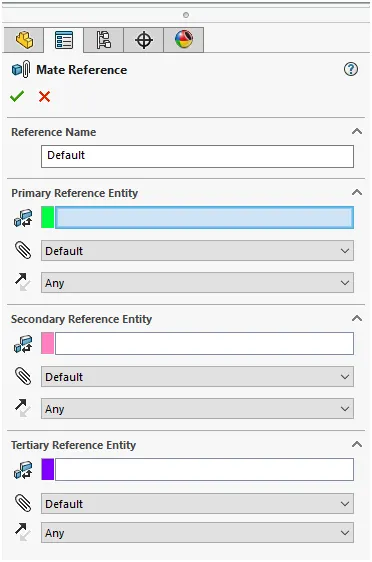
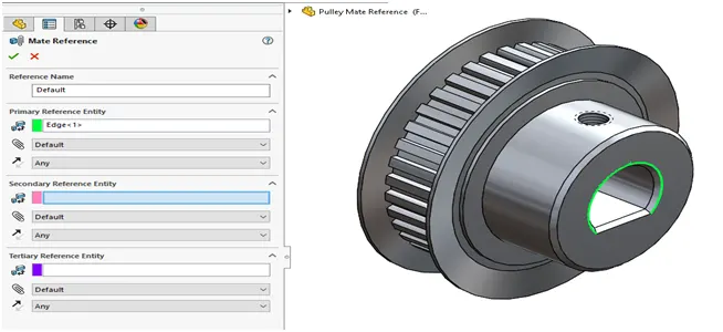
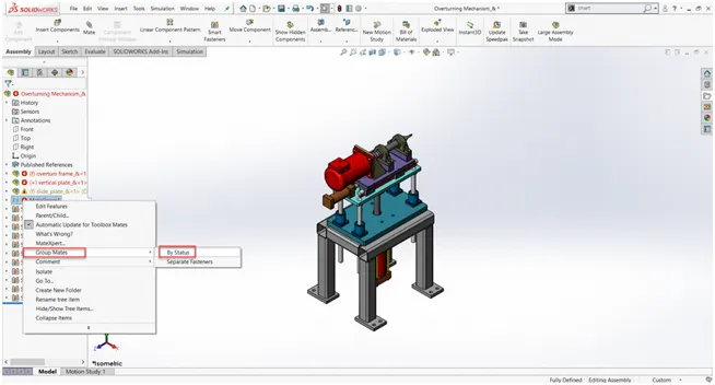
As the Above we Have discuss all the Feature tree Using in Solid Works while Designing Any Component In solid works . Now We have discuss the all features Properties while Making All the Component Of American Chopper Bike .Let us discuss Below Every Part Component Step By Step.
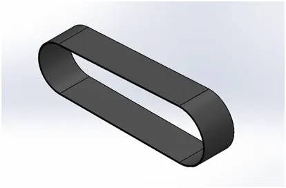
- TRANSMISSION BELT :
Step1- Create a2D sketch based on the vertical cross section of the Transmission belt and make sure They are in relation to each other and dimensioned correctly.
Step2-Create an extrude by selecting the sketch loop and then specifying the dimension of the extrude. use fillet tool to give the transmission Belt a smooth finish.
Step3- select appearance tab specify the material for the Transmission Belt Rubber matte.
Step4- Save the part .
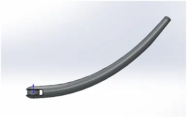
- KICKSTAND:
Step1- Create a 2D sketch based on the cross section of the thick portion of the kickstand, then use spline function to draw the guide way for the loft and then finally add a plane normal to the direction of our spline. After creating a plane create a 2D sketch based on the cross section of the thin portion of the kickstand and create a loft across the guide curve .All the sketch are in relation and dimensioned correctly and the sketch is fully defined.
Step2- use the dome tool to create a curved shape at both the end sections, and then extrude cut to create a cut near the thick portion of the kickstand so that it can be attached to the pivot. after that split feature used .To create pivot point to attach to the frame we will create cylindrical section near cut out of the kickstand.
Step3- Fillet the edges for a smooth finish and in the appearances select chrome plate .
Step4- Save the part as a kickstand.
3 .FRONT FENDER :
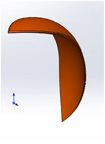
Step1- Create a2D sketch based on cross section of the front Fender and then use the revolve tools by specifying the angle of revolving in both the dimensions.
Step2- Sketch the design of the cut out portions at both the end section of the front fender.
Step3- Fillet the edge of the front fender .using appearances under painted car siena colour .looking very stylist .
Step4- Save the part as Front Fender.
4.REAR FENDER:
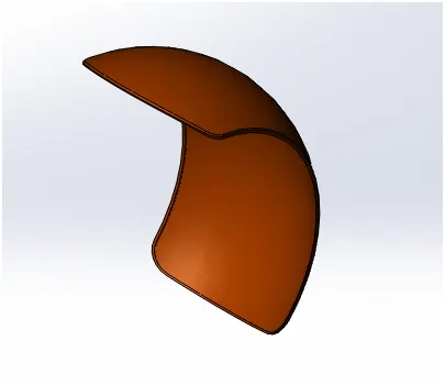
Step1- Create a2D sketch based on cross section of the Rear Fender and then use the revolve tools by specifying the angle of revolving in both the dimensions.
Step2- Sketch the design of the cut out portions at both the end section of the Rear fender.
Step3- Fillet the edge of the Rear fender .using appearances under painted car siena color .looking very stylist .
Step4- Save the part as Rear Fender.
- CHAIN:
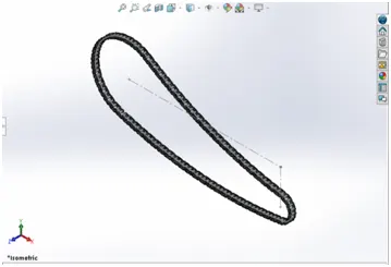
Step1- Create a 2d sketch using of line and arc tools making the outer edges of the chain link.
Step 2- Create the front and back link of a chain and saved as a block diagram to use continuously with the relation of concentric to joint of the path . Determine how much block diagram needed to complect the curve by using our mouse middle botton scrolling until the entire loop complected.
Step3- After that mirror the face of the links to the pins in the block diagram with respect to the mid plan. A fine finished chrome plate metal is used as the appearance of the linked part.
Step4 - Save the part .
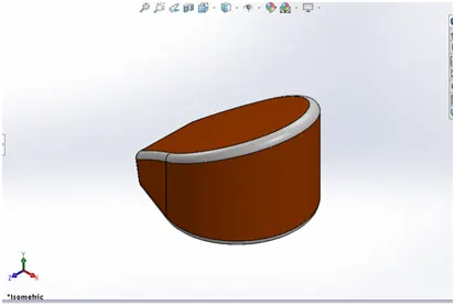
- OIL TANK:
Step1- Create a2D Sketch based on the Top plane and extruded . Again create a sketch on the mid plane and extruded .
Step2- After that Extruded The Sketch Combine Feature used and combine both the extrude together. And another feature is used that is shell feature is used to make the part hollow and edges are fillet.
Step3- In the appearance tap use same as siena colour In the body .Fillet edges are painted as White paint.
Step4- Save the part .
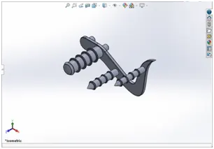
- PEDAL:
Step1- Create a 2D sketch based on Front plane the base of the pedal ,and then extruded boss is created with dimensional circular hole for the foot rest. And pins extruded again .
Step2- Now create a sketch on the top plane and revolved . And Now applied Dome Feature and filleted the edges.
Step3- After that the front and rear extruded cylindrical part chamfered . circular pattern is extruded on each of the front facing extrudes which are then arranged using linear patter. And filleted edges.
Step4- save the part.
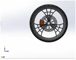
- FRONT WHEEL:
Step 1- Create a 2D sketch on front plane . Then using revolved feature for making tires . After that using the Extrude Boss Feature for making or create the Rims Calipers ,Rotor ,Sprocket.
Step2- Now we using the Extrude Cut feature for remove the additional materials from the extruded rims for the spider webbed design.And also for cut out from the sprocket rim rotor. After that we using Cut Revolve to cut out the side sections.
Step3- Then Using circular pattern in the sprocket, Rotor, Rim Tire Grip Design..
Step 4- Appearances uses to specify the materials of various part.
Step5- Save the part.
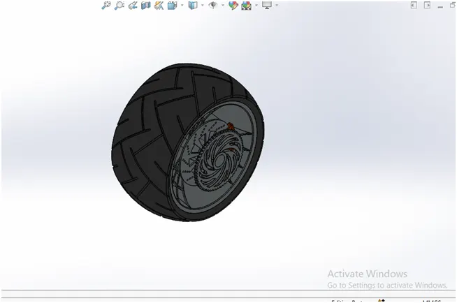
- Rear Wheel : The designing of both the wheels are similar the differences is in the size of the wheel.
Step1- Create a 2D sketch on front plane . Then using revolved feature for making tires . After that using the Extrude Boss Feature for making or create the Rims Calipers ,Rotor ,Sprocket viz.
Step2- - Now we using the Extrude Cut feature for remove the additional materials from the extruded rims for the spider webbed design.And also for cut out from the sprocket and rotor. After that we using Cut revolve to cut the side section from the extruded rims for the spider Webbed Design.
Step3- After that we using circular pattern in the sprocket, Rotor, Rims Tire Grip Design.
Step4- Appearances uses to specify the materials of various part
Step5- Save the part.
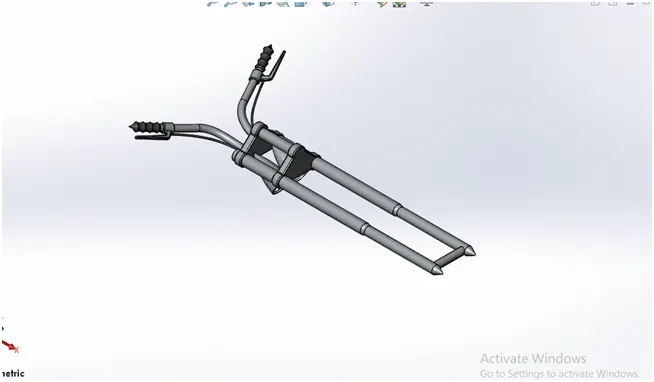
9.FRONT FORK:
Step1- To Create a 2D sketch On a Front plane .And by using Revolved Boss feature to create fork tube . Again create a sketch and create handle grip by Revolve boss Feature. In this Revolve Boss Feature We create Head light .
Steep2- We using Extrude Boss to create the Triple clamps ,Breaks viz.
Step3- In this Extrude Cut Feature we create circular cutouts for the triple clamps. And use another feature that is dome to create the dome shape of the headlight.
Step4- To create the two portions of the triple clamps by using linear pattern feature. we create the complex shape of the Bike Handle bars &the Break Wires ,Projected curve was used to create the path for the sweep command and then the sweep too we used from the feature tab to complete the Bike Handles .the same procedure was used to design the break wires.
Step5- Appearance to specify the materials of various part.
Step6- Save the part.
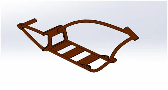
- CHASSIS:
Step1- Before Creating Sketch We also Rename the Plane For Better Understanding . Now Create a 2D Sketches on the Mid plane Chassis. The Sketch Based On the Reference blue Print Of the American Chopper.
Step2- Extrude feature was used to create plate sections of the chassis. And then used Sweep feature to design the chassis cylindrical structures of the chassis.
Step3- Projected curve features was used to create the sweep paths of the complex geometry. Then using Extruded cut Feature to cut the Extra portions of the Extruded bodies.
Step4- After that we using Revolve cut functions to create the cylindrical geometries and to cut out unwanted portions from the revolved parts . some other features used included Mirror ,Dome, Fillet , Chamfer.
Step5- In Appearances Tab we use Siena color .
Step 6- Save the part.
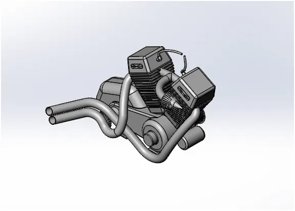
- ENGINE :
Step1- Initially ,2D sketchs were drawn through the reference of blueprint of chopper image and the extruded feature is used to create each part of the engine like a sprocket, engine cylinder ,engine exhaust system.
Step2- Chamfer feature ids used to create the tapering design of the two engine cylinder.
Step3- The sweep ,projected curve feature is used to create the complex geometry path for the sweep, split ,extrude cut, revolve feature were used to create the air Filter and the Exhaust manifold.
Step4- The linear pattern feature and circular pattern werte used to design the cutout sections of the row of fins on the engine cylinder and the the circular cutouts fpr the sprocket respectively. Some other feature were used like as mirror, dome ,fillet.
Step5- Save the part.
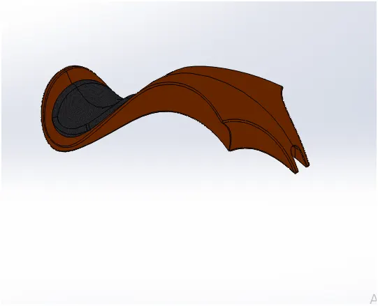
- GAS TANK:
Step1- To create a2D sketches with Based on the Blueprint chopper image. Creating a 2D spline sketch its Surface sweep Feature was used for making the outer layer of the Gas tank.
Step2- The split line was usd to remove the unwanted part by designing the shape to be cut.
Step3- Surface Knit feature were used and then Combine the Surfaces of the gas tank.
Step4- And then using a surface loft is created as the front face of the tank now with the help of boundary sweep feature the front face and the side face are joined. A sketch is drawn at the face of the gas tank to cut the u section all the sharp ends are then filleted a shell is created at the end to make it hollow. Other tools used like cut sweep.
Step5- In the Appearances Tab we were used siena color .and for seat material we used Grey cotton .
Step6- Save the Part.
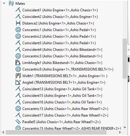
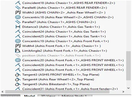
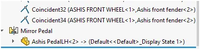
- AMERICAN CHOPPER ASSEMBLY: The Different Assembly Parts are opened and then assembled in the assembly window by using different mate options like as coincident, concentric, angled, parallel ,limit angel, tangent, width mate etc.
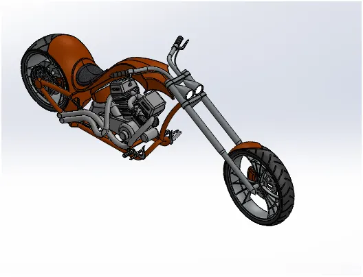
- RENDERING: At the end of Assembly we reach the final step of the bike to make sure to look the bike as realistic view. Initially make sure your assembled part in the correct position in which you want to be . In this case we want to the chopper to learn on the stand to make sure the chopper is slightly tilted towards the stand so that it gives a more realistic look. Using photo view 360 try different environments based on the project you are looking on. After selection of the environment make sure all the shadows light camera settings are set perfectly .Finally select the resolutions of your render, pixel, density and perform the final render. We can also use solid works visualize for more realistic renders. The parameters are same but the Solid works gives more options for rendering like HDR background selections, camera settings, more options in the material selections. Finally save your Rendering.
CONCLUSION:
All the parts of American chopper were modeled and the assembly was created in using solid works and photorealistic render was created using solid works visualize .