Advanced Sheet Metal Design Using NX Cad Challenge_1_Casing Design
CASING DESIGN USING NX SHEET METAL 12
DESIGNED BY
ASHIS TARAI
LINK:https://drive.google.com/file/d/1E5qvwlRkVjuKFUkXdW-U33xvXCSU_cHo/view?usp=sharing
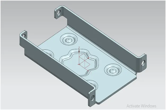
OBJECTIVE: In this tutorial we will learn step by step procedure t o design a sheet metal casing using Siemens NX sheet metal application.
INTRODUCTION:
Sheet metal is metal formed by an industrial process into thin flat pieces. Sheet metal is one of the fundamental forms used in metal working and it can be cut and bent into variety of shapes. Sheet metal are using in various industry like Automobile ,Aeronautics medical tables, beverage cans. Countless everyday objects are fabricated from sheet metal. thickness can vary significantly extremely thin sheets are considered foil or leaf, and pieces thicker than 6mm are considered plate steel or structural steel.
Here we constructing a cad model of sheet metal casing in NX cad software .Design methodology used to construct this sheet metal casing design described below.
APPROACH:
DESCRIPTION –
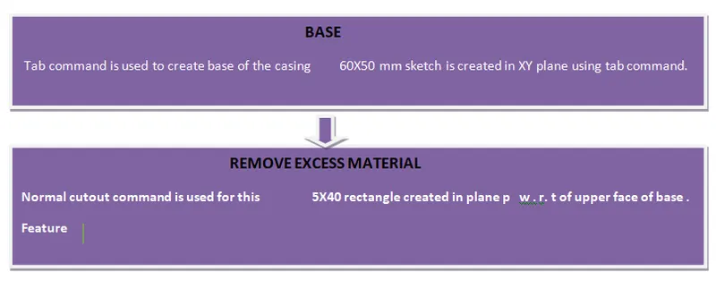
1> SKETCH:- 2D sketch commands is used to create any sketch. Sketch is the base feature of any sheet metal design.
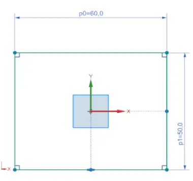
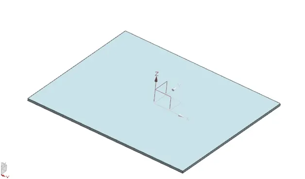
2> TAB:- primary base feature of the casing .Tab command in NX sheet metal work bench used to create any sheet metal casing.
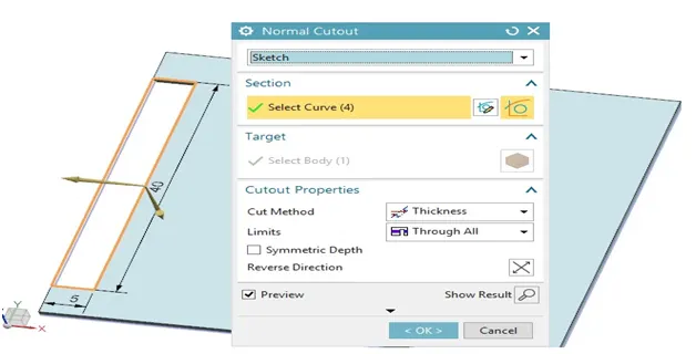
3>NORMAL CUTOUT:- it is used to cut the specific portion of the part .It is required sketch to perform the operation.
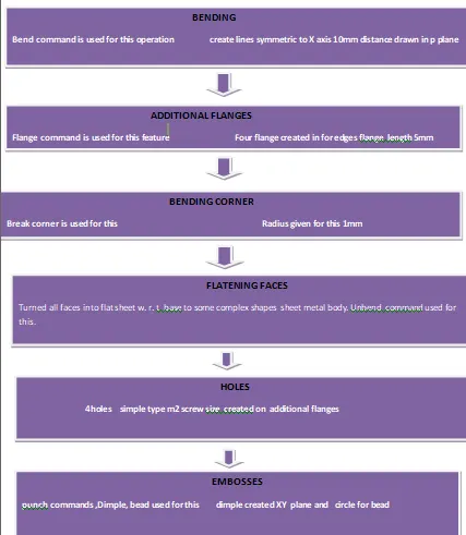
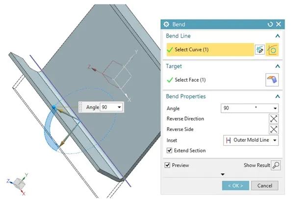
4>BEND :- Here a horizontal line was drawn to bend the face of the part of the specific angle.
5>FLANGE:- Flange is the secondary Feature .It needed base feature to perform the operation .It just needed an edge of the base to create secondary flange.
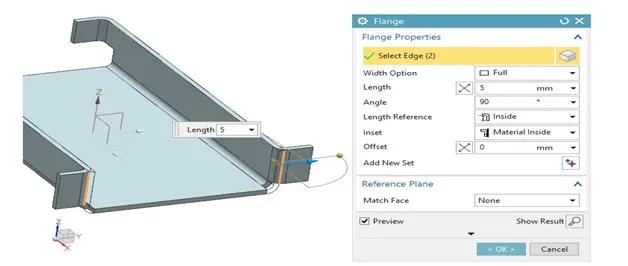
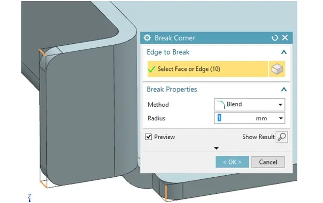
6> BREAK CORNER:- :- Machining corner between two major element of contour is called corner breaking. Break corner tool is used to blend or chamfer specific radius or distance and angle.
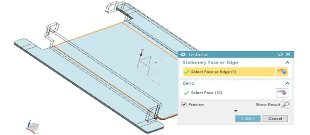
7> UNBEND :- The operation is performed flattening all the faces of sheet metal part to create some complex structure.
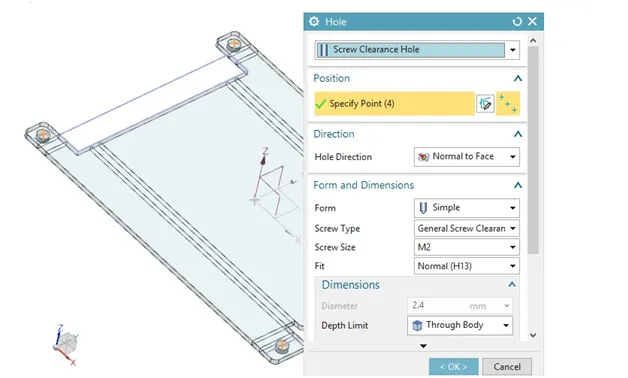
8> HOLES:- Holes are created for fitting purpose. Various screw holes of size created through this tools.
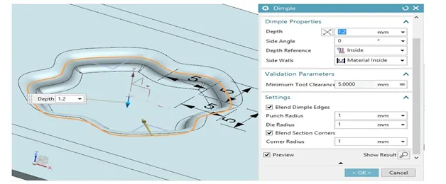
9> DIMPLE:-Dimple is a punch tool used to create emboss over sheet metal part. It needed a sketch to perform.we can create sketch over the plane parallel to the surface of the sheet metal where we want to give emboss .
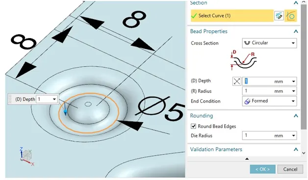
10> BEAD:- Bead is another punch tools used to create embosses over the sheet metal body w. r. t the sketch created in specific planes.
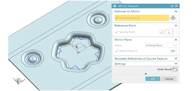
11> MIRROR :- Mirror is a feature to create copy of some feature to minimize the design feature ,time and effort.
You can mirror exiting feature expect for legacy intense arrays ,legacy intense feature ,legacy mirror feature.
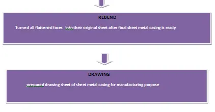
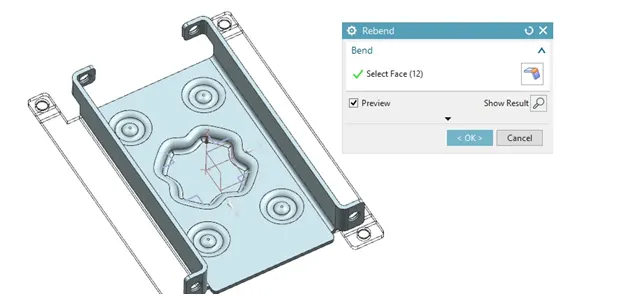
12>REBEND :- It is a toll to get the flange of the sheet metal body into its original position that are flattened with unbend tool to create some complex structure
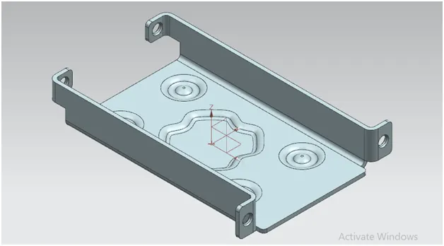
FINAL SHEET METAL CASING DIFFERENT VIEW IMAGES
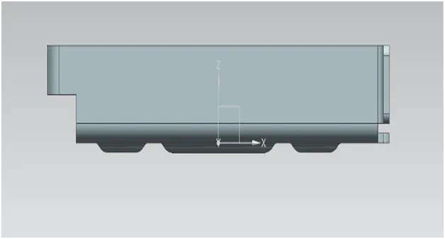
FRONT VIEW
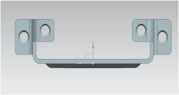
SIDE (LEFT VIEW)
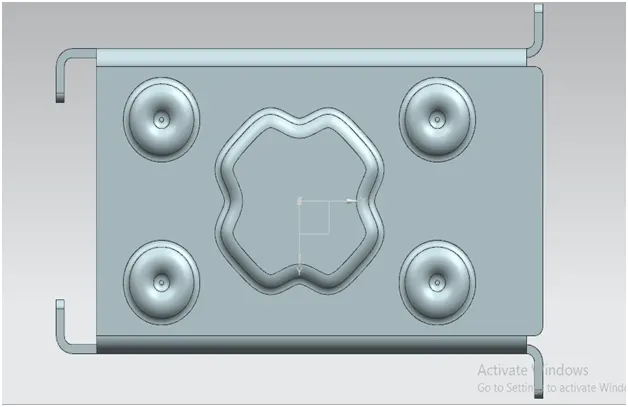
BOTTOM VIEW
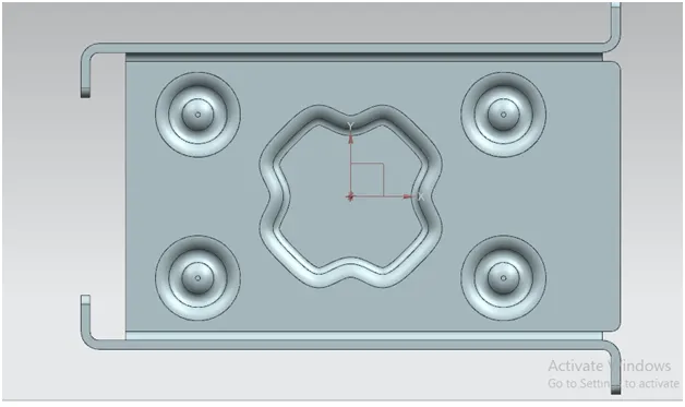
TOP VIEW
ISOMETRIC VIEW
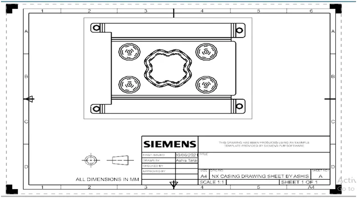
DRAWING SHEET
CONCLUSION:
By doing this challenge i learn basic feature of sheet metal design using of feature like tab flange bend punch tools etc. i learned the design approch that should follow the construct this type of sheet metal part.