Advanced Sheet Metal Design Using NX Cad Challenge_2_Box Assembly
BOX ASSEMBLY DESIGN USING NX CAD
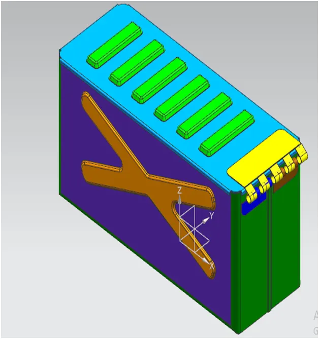
DESIGNED BY ASHIS TARAI
LINK: https://drive.google.com/file/d/14cDivcxw8VRaNkWj7kMSLXAZhTw1H7fY/view?usp=sharing
OBJECTIVE:-
To design sheet metal Box Assembly using NX cad 12
INTRODUCTION:-
Sheet Metal is a metal forming process through industrial process into thin, flat pieces. Here I have created a sheet metal box assembly of various thickened part Box assembly contained 3 main part .
1> box (base part)
2> Box Lid
3> Hinge
To design this using different method and features.
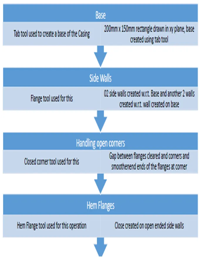
DESIGN METHODOLOGY :
DESCRIPTION:
This Box assembly has 3 part I have described these process step by step below .
A> BOX :-
1 . SKETCH : Making a 2d drawing such as circle arcs, curves, points, rectangle, and many option to create a drawing or to create feature for upcoming designing.
200X150mm rectangles created on XY plane of Datum coordinate system.
- TAB: Base of the Box was created using sketch drawn in XY plane.
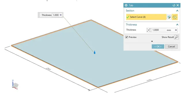
3> SIDE FLANGE: Side walls of the box created using flange option .It adds an angular or flat surface on the edge of the surface to create an extruded surface with a required direction.
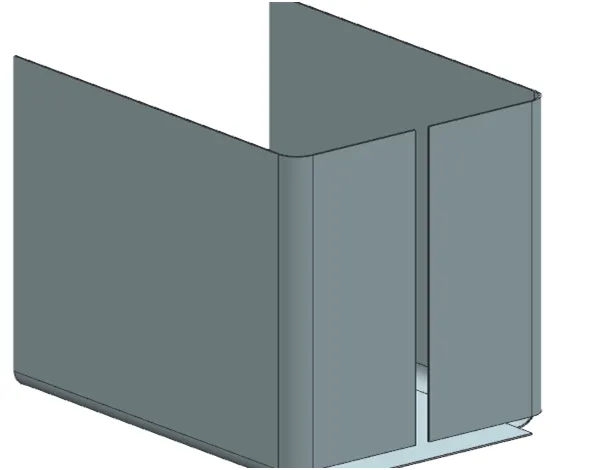
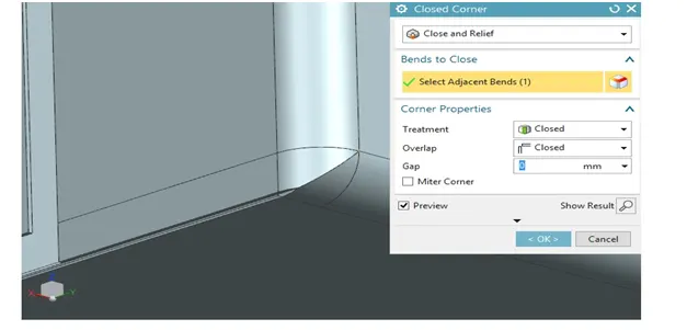
4> CLOSED CORNER : This tool used to provide smooth corner by removing intersection ,handling gaps , smoothing ends of the flanges.
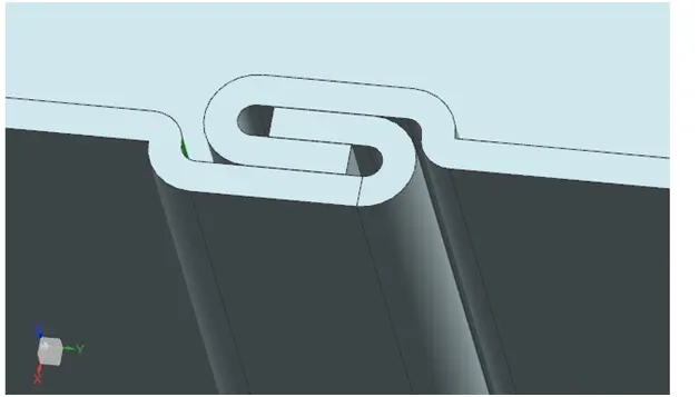
5> HEM FLANGE : Closed loop of hem flange created at the open ends of the side walls to close the gap between flanges of side walls.
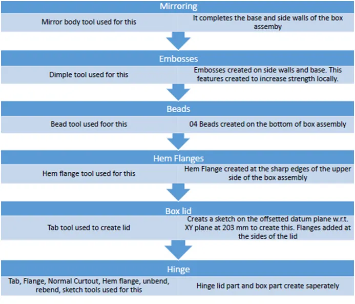
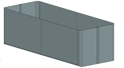
6> MIRROR BODY : Body of the box completed by mirroring body.
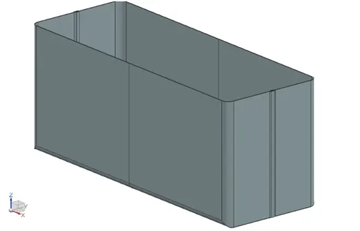
7> UNITE: After using mirror body 2 separate body created .This tools united two separate bodies.
8> DIMPLE : It is to lift an area shown on the sketch to create an Impression of the sheet metal.
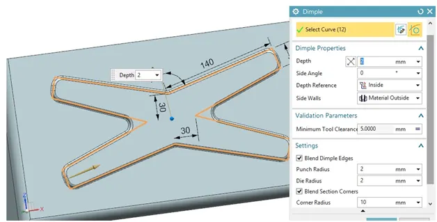
9> MIRROR FEATURE : Emboss created on other side of the box created by using mirror feature .This is a different tool than mirror body but has same purpose. It mirror feature that created on the body while mirror body mirror the whole body.
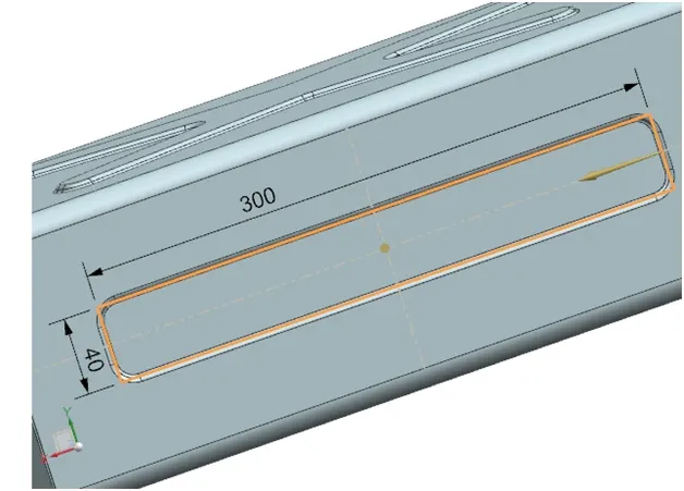
10> DIMPLE: Again used dimple tool to create emboss on the bottom of the box. I have drawn a rectangle on the bottom face of the box create dimple here.
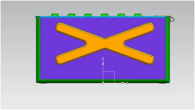
11> BEAD & MIRROR FEATURE : Bead created on the bottom of the box .
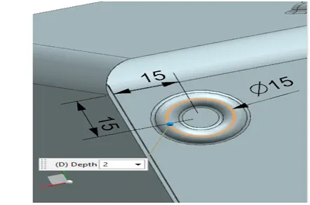
This feature has been mirrored and created 4no of bead
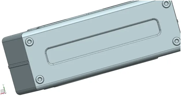
12> HEM FLANGE : Hem flange created of the sharp edges of the box side walls.
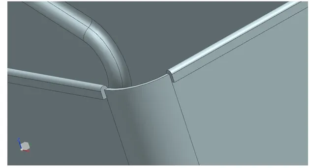
Final model of box completed.
B> BOX LID :
1> DATUM PLANE : Datum plane w. r. t XY plane of Datum coordinate system to an offset of 203 mm created .
2> SKETCH : I have created sketch on above created datum plane as a reference of box lid.
3> TAB: Box lid created using tab tool.
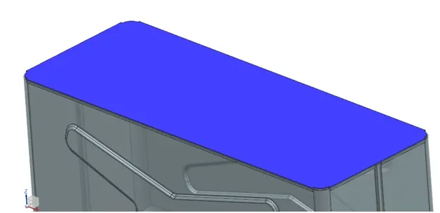
4> FLANGE : Flange added at the two edges to complete the box lid.
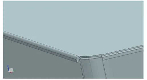
Box Lid completed.
C> HINGE: Here Hinge created in Two parts-
- Box Part
- Box Lid part
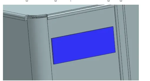
1> TAB: Base flange of the hinge box part created using flange tools. Sketch as on the side wall of the box.
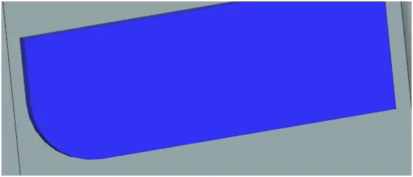
2> BREAK CORNER : Corner blended with 10mm radius.
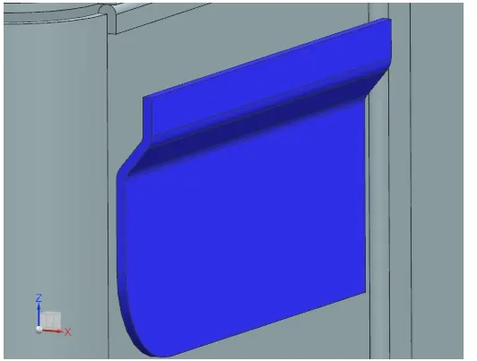
3> FLANGE: 2additional flange created on w. r. t base flange created above.
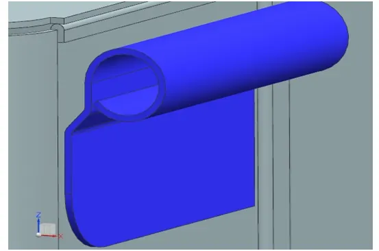
4> HEM FLANGE : open loop of hem flange created
5> UNBEND NORMAL CUT OUT AND RE BEND: Flattened Hinge Portion to perform normal cutout and to re bend to get hinge in it original position.
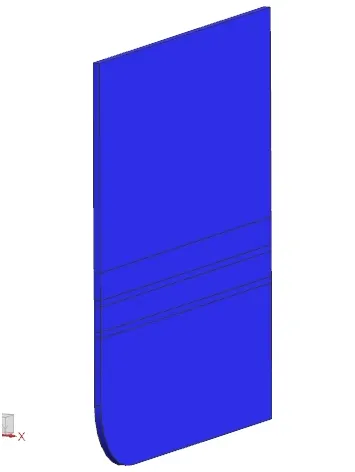
NORMAL CUT OUT
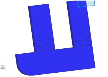
RE BEND
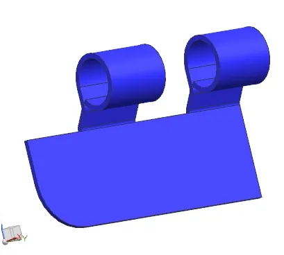
6> MIRROR BODY:
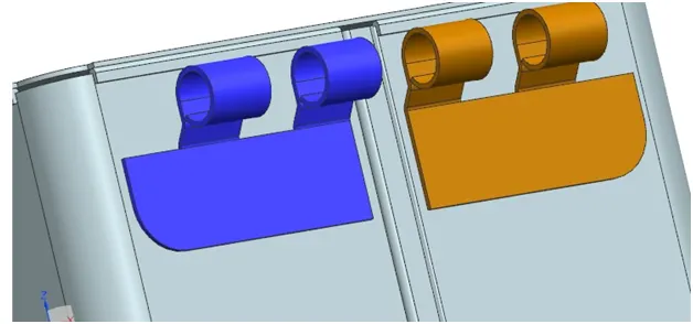
Hinge part completed
7> TAB: Base flange of the hinge Lid part created using tab tool .Sketch cresated on the upper face of the lid to perform tab operation.
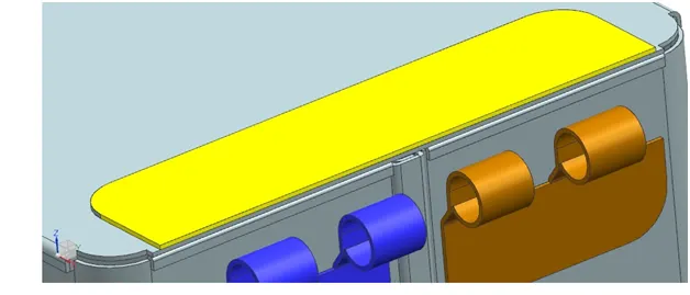
8> FLANGE: Additional flange added using flange tool.
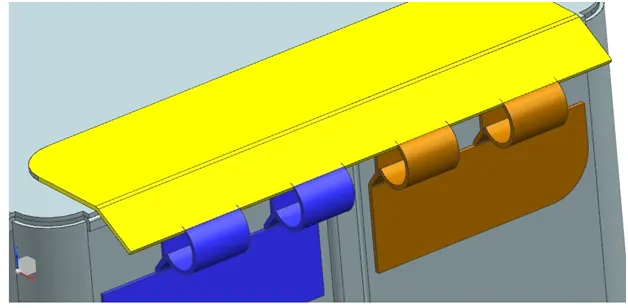
9> HEM FLANGE: open loop of hem flange created.
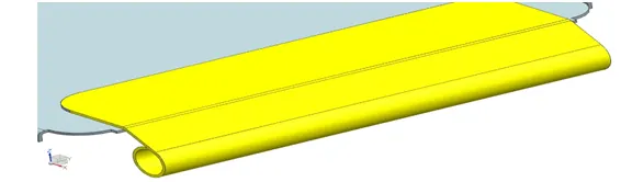
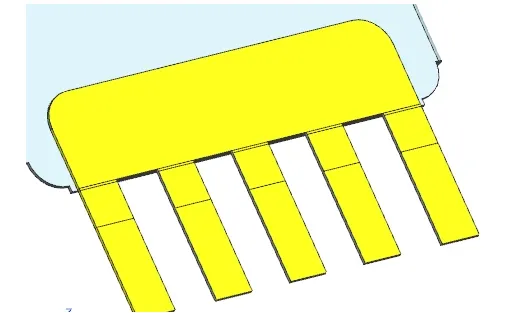
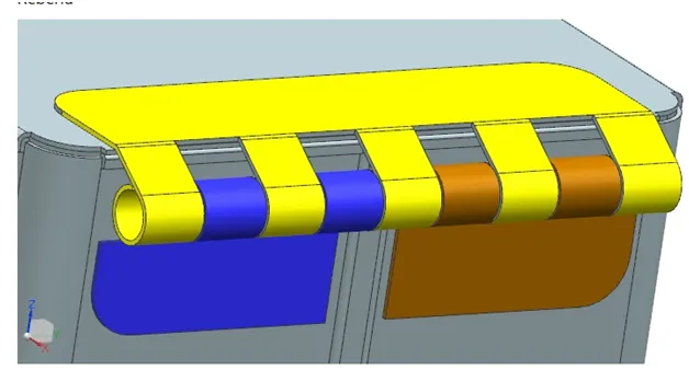
10> UNBEND , NORMAL CUTOUT ,AND RE BEND : same process done while creating Hinge part.
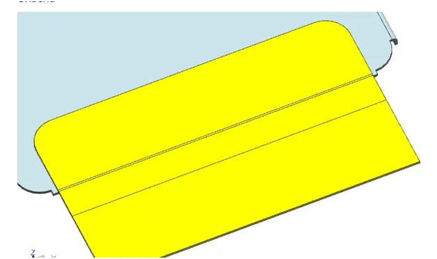
NORMAL CUTOUT
RE BEND
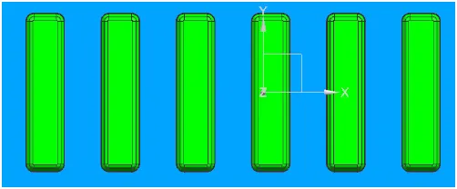
11> DIMPLE: Dimple was created at the top of the box .and make pattern.
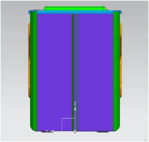
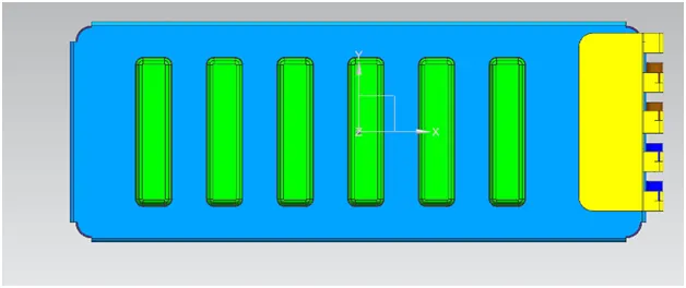
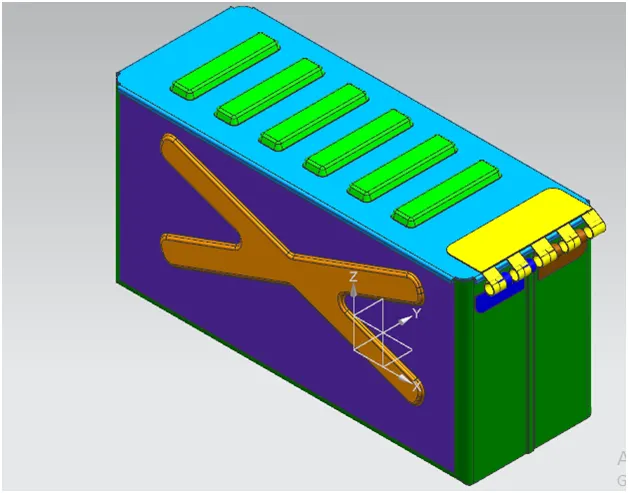
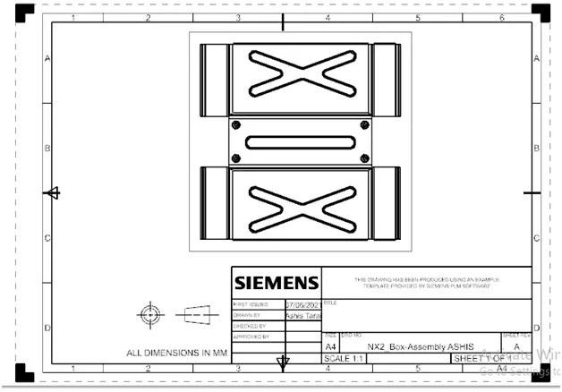
Here final Box assembly created
FRONT VIEW
LEFT VIEW
TOP VIEW
ISOMETRIC VIEW
DRAWING SHEET
CONCLUSION : By doing this project I have learned some new sheet metal tool feature and understand the design methodology to create this type of sheet metal part.