Wiring harness design in CATIA V5 - 3D modeling Week 4 Challenge
Introduction
A Wire Harness is a grouping of wires, cables, or subassemblies designed to transmit signals or electrical power. A wire harness is typically designed to simplify the manufacture of a larger component, and is designed based on the geometric and electrical requirements of the equipment it is to be installed in. Image below shows wire harness assembly
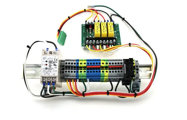
Wire harnesses are commonly used in the electronics industry, the automotive industry, in the manufacture of construction machinery and industrial equipment, as well as in the manufacture of white goods such as washing machines and dryers, refrigerators, and other household appliances.
Wire harness assembly design in CATIA V5
- Preparation of harness assembly: Wire harness assembly contains
- The harness context assembly: This is the top level product file that contains the harness geometrical bundle/assembly and the wire harness electrical bundle.
- Geometric bundle: This is sub-level product file of the wire harness product that contains all of the harness components i.e., clips, supports, connectors, splices, grommets, annotation and actual physical bundle segments and branches
- Electrical bundle: This sub-level product file contains all of the electrical circuit information.
Creating wiring harness assembly contains following steps:
- Create new product file and give name wire harness assembly
- Under this product file, create another new product file and give name as ‘Geometrical Bundle’
- Under wire harness assembly product file, create new product file name it as ‘Electrical Bundle’
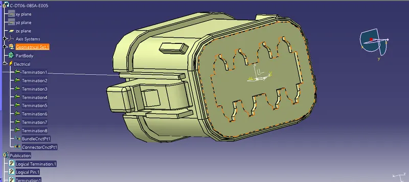
- Download the connector 3D data and define all the connectors as electrical components. Then define all the necessary connection points in the connectors. Images below shows the completely defined connectors. Images below shows the electrically defined connectors.
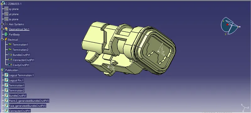
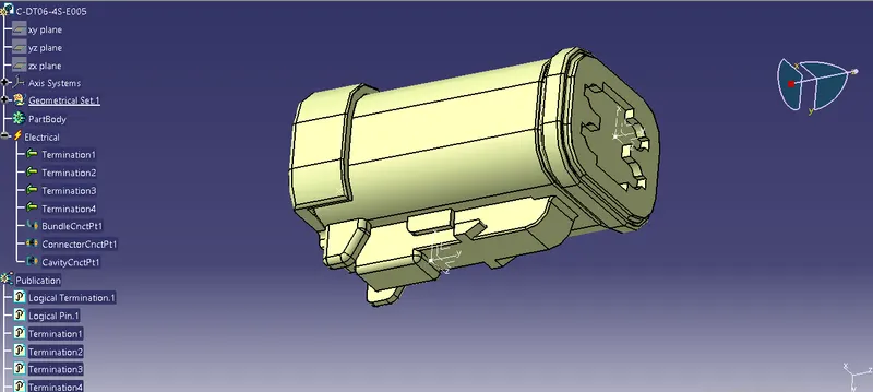
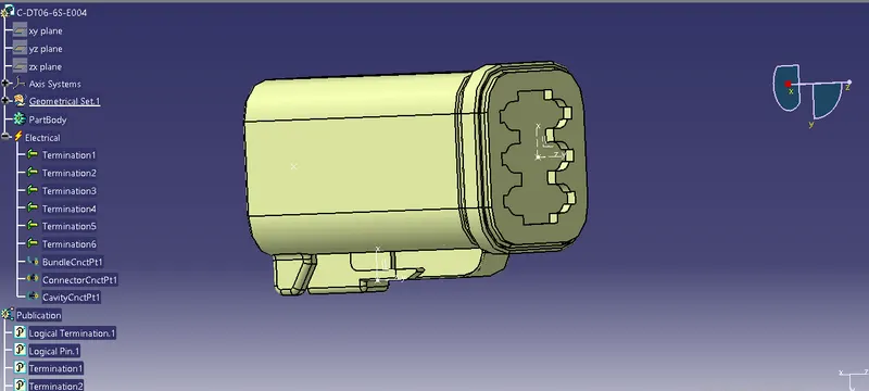
- Import all the connector components into the ‘Geometrical bundle assembly’
- Define the ‘Mechanical assembly’ into ‘Electrical assembly’
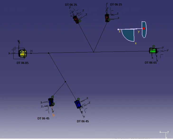
- Ensure that all the electrical parts inserted are now in ‘Geometrical Bundle’. Now place each electrical part into its correct position. There are five ways for moving and positioning the electrical wire harness components. They are ‘Manipulation’, ’Translation and Rotation’, ‘Snap’, ‘Smart move’, ‘Move components using Compass’. In the present case, go to the ‘Part design workbench’ to draw the positions of the connectors.
2.Wire harness routing: It deals with desired path of wiring harness into given vehicle environment by applying set of design rules and industry best practices. This involves following steps:
- Switch to the electrical harness assembly workbench
- Ensure that your harness geometrical bundle is highlighted
- Select the ‘Multi-branchable document icon’
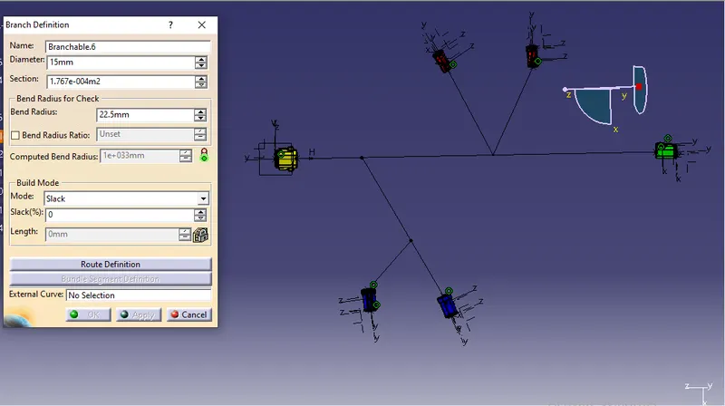
- In the branch definition box input all the required parameters
- Ensure that the bend radius ratio is set to 1.4 or greater than 1.5
- Ensure that the build mode is set to ‘Slack’
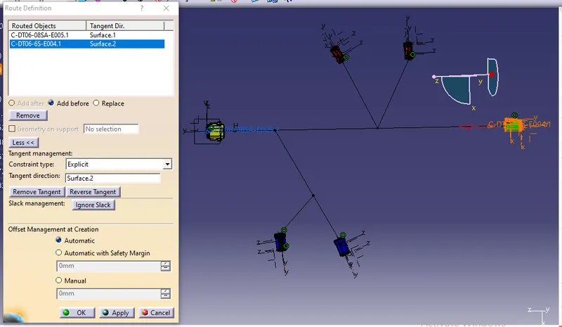
- Under ‘Route definition’ box insert the electrical components between which you want to establish electrical connection. Ensure proper routing direction is set. Harness bundle diameters are set at 15 mm.
- To add branch point, Double click on ‘multi-branchable’ in model tree. Select ‘Add branch point’ icon in ‘Electric harness installation’ workbench. Click on the branch of wire harness assembly. Then set the distance. Image below shows the all branches added.
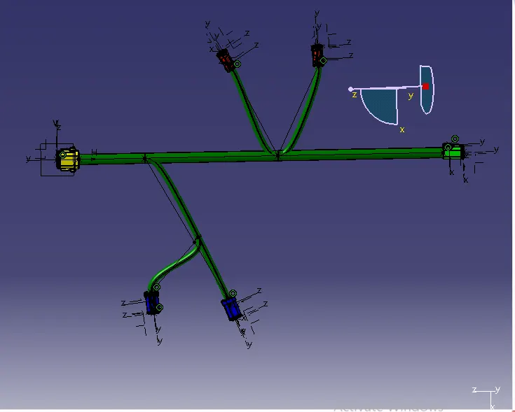
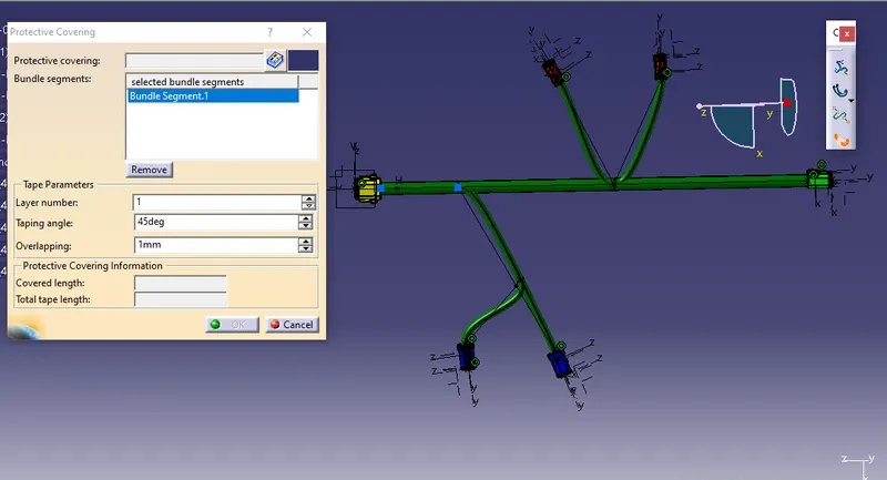
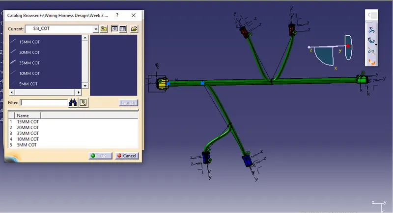
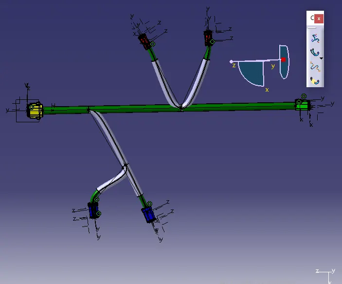
- To add protective coverings, select ‘Protective covering’ icon in ‘Electric harness installation’ workbench. Select the branch to which covering is to be added. Select the required covering from the catalogue. Set the ‘Start and End extremities Points’ if required.
Conclusion
- Wiring harness routing is carried out as per the given harness layout in electrical workbench. Also protective coverings are added on all branches connected to DT06-2S & DT06-4S connectors