Wiring harness design in CATIA V5 - 3D modeling Week 2 Challlenge
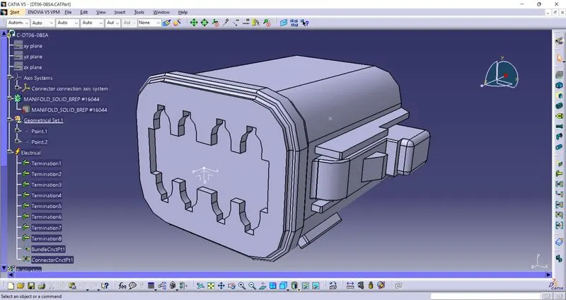
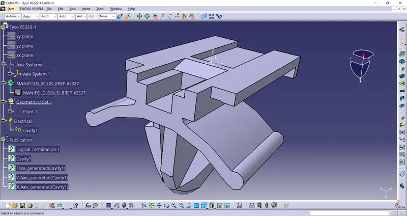
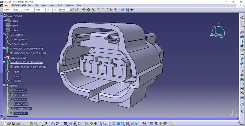
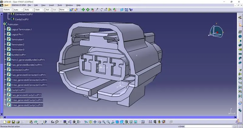
Steps followed to define connectors & Connector clip as an electrical part in electrical part design workbench.
1)Download the connectors and clip from the link in stp format and load them in catia(DT06 – 08SA, Tyco 174357-2, Tyco 85229-1)
2)Create the Geometrical set like point at the bundle entry side,mating side and cavity side. Also create the axis system at the mating side and cavity side. Ensure the consistency of the axes system in the mating parts too.
3)Switch to Electrical part desing module to define the connector and clip as an electrical part.
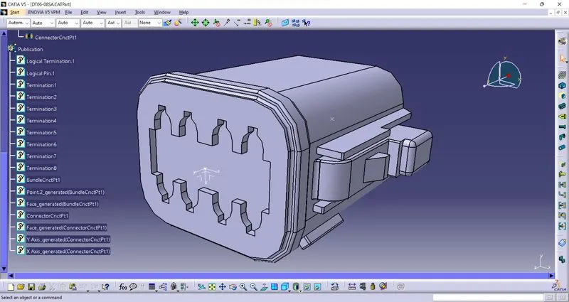
4)Use "Define Connector" command to define the connector and "Define Mounting equipment" to define the clip.
5)Now use "define Bundle connection point, define Connector connection point, define cavity conncetion point" commands and choose the appropriate points, faces and axes to the Bundle connection point, Connector connection point and cavity conncetion point. Use "Define cavity" command for the clip.