Wiring harness design in CATIA V5 - 3D modeling Week 2 Challlenge
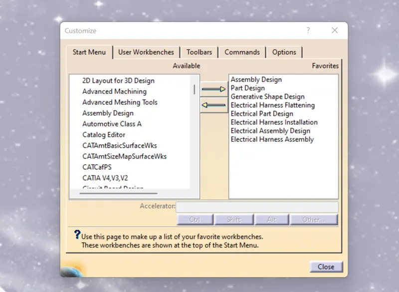
Downloaded the required files from TE.com. website in IGS files after that open those files in CATIA. For designing the Wiring harness in Catia we have to do some CUSTOMIZE for Catia.In my case, I added what are the required workbenches I added to my Catia welcome page
Then I converted.IGS files too. part files and opened in Catia part workbench
To define connecter as electric properties, we need to create some geometrical features like Points and Axis
To Create point and axis open the connector(c-dt06-08sa-99-3d) in the Catia part workbench click on the point command and select BETWEEN option and select the points and select the Middle point then create the axis system based on the point and repeat the same process to the opposite side of the connector for Bundle entry point.
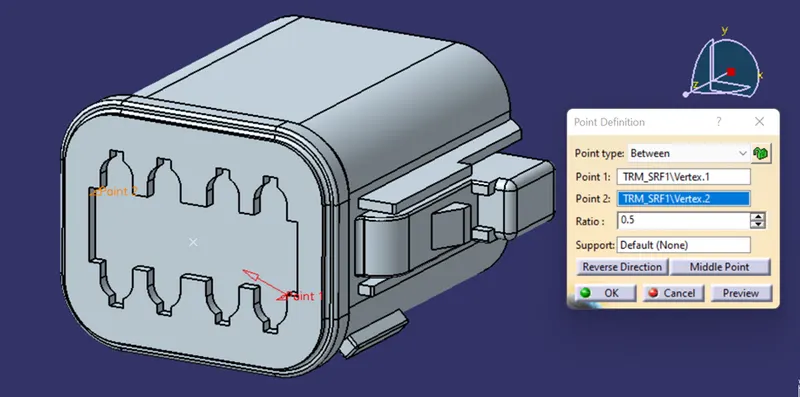
Fig point creating
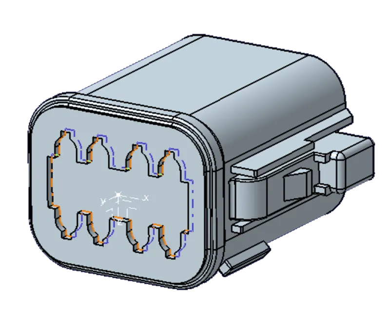
Fig creating of axis system
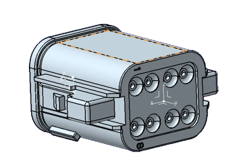
Fig creating of axis system for Bundle Entry
Then change PART DESIGN WORKBENCH to ELECTRIC PART DESIGN WORKBENCH and define the part as select the DEFINE CONNECTOR command and select the component and enter the number of Terminals in the connector and select OK. The component is defined as the ELECTRIC COMPONENT.
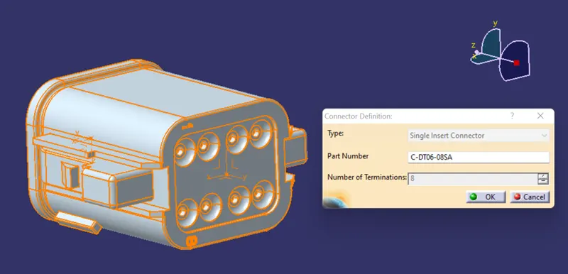
Fig Defining of Electric Component
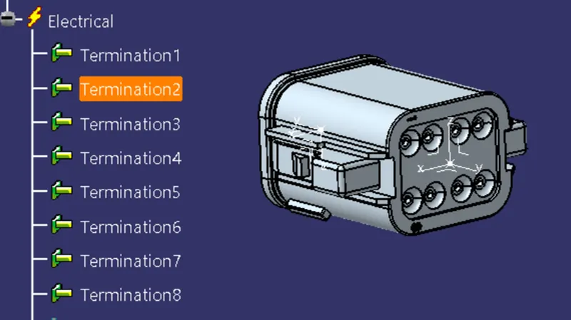
Fig Electrical Geometrical Set Created
Now define the Bundle Entry point by selecting the DEFINE BUNDLE CONNECTING POINT and select the component the popup window opens in that select the representation face as connector Bundle entry face and point as we created and Initial condition as the face of the connector. select OK In the Electrical geometrical set Bundle entry was created.
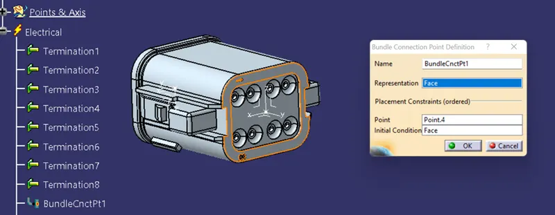
Fig creating Bundle entry point
Now create Connector Entry Point by selecting the DEFINE CONNECTOR CONNECTING POINT command and select the component a new window popup in that in select the representation point as created point and connect as face and coincidence as Y-axis and orientation as X-axis and select OK.
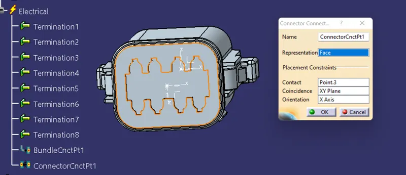
Fig creating Connector entry point
And save the file and added to the catalog by selecting the store device command in the Electrical part Design work bench.
Repeat the same process for the component(C-2-174357-2)
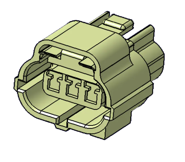
Fig C-2-174357-2
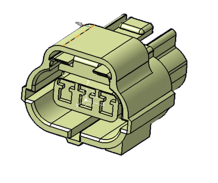
Fig point creating and Axis Creation
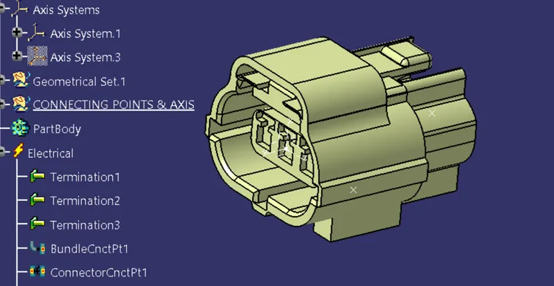
Fig creating of Bundle Entry and Connector Entry
There is an extra process for this component is to define the clip attachment point for that create the point on the clip attachment by using the ON CURVE option at point command and use the middle option at the points and define as the CAVITY CONNECTION POINT.
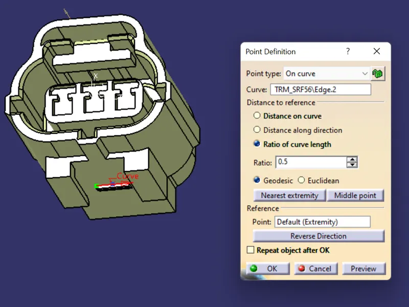
Fig Define the point for Clip
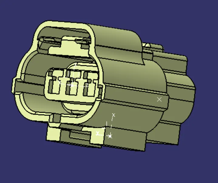
Fig Creating axis for the Clip
And move to the electric part workbench and select the DEFINE CAVITY CONNECTING POINT and select the point as representation and face as contact and coincidence as Y-AXIS and orientation as X-axis save the connector and added to the catalog.
For the clamp point and axis, creation is the same as shown above there are some changes while defining the point for defining the clip select the DEFINE WITH MOUNTING equipment in the command bar. And select the component and select the DEFINE THE CAVITY option in the command bar. Select the command similar to the above cavity select ok save the component and add to catalog.
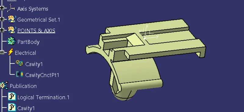
Fig Defined clip
Open the electric product file and open the catalog and import the file from the catalog and make a connection for the two parts in the Electric Assembly Design and select the Electric connection command and select the one component and then select the other component then the connection was formed with each other.
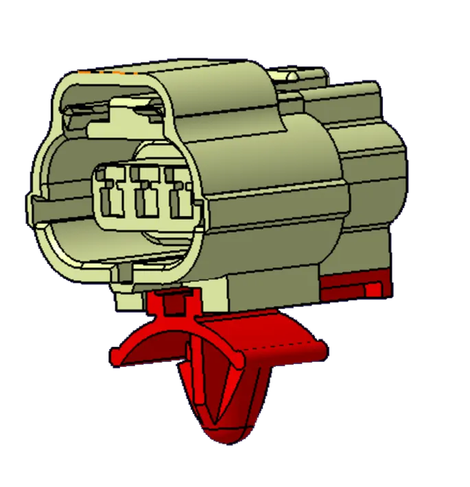
Fig Connection Created with Clip and connector