Wiring harness design in CATIA V5 - 3D modeling Week 2 Challlenge
Introduction
Electrical connectors are electromechanical devices used to join electrical termination and create electrical circuits. These are plastic molded housing with locking and retention features. Electrical connectors consist of housing, terminals, wedge locks, seals, cavity mounting cam etc. Most electrical connectors have a gender – i.e. the male component, connects to the female component.
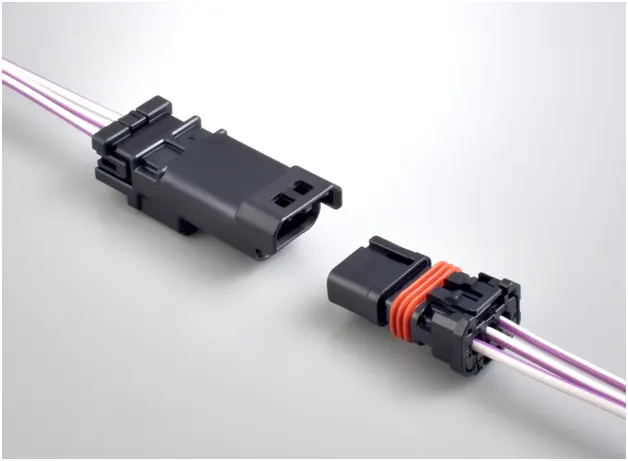
The connection may be removable (as for portable equipment), require a tool for assembly and removal, or serve as a permanent electrical joint between two points. Thousands of configurations of connectors are manufactured for power, data, and audiovisual applications.
Properties important to connector materials are contact resistance, conductivity, mechanical strength, formability, and resilience. Electrodes in connectors are usually made of copper alloys, due to their good conductivity and malleability. Alternatives include brass, phosphor bronze, and beryllium copper. The base electrode metal is often coated with another inert metal such as gold, nickel, or tin. The use of a coating material with good conductivity, mechanical robustness and corrosion resistance helps to reduce the influence of passivating oxide layers and surface adsorbantes, which limit metal-to-metal contact patches and contribute to contact resistance.
Procedure to define a connector in CATIA V5
1. Create / Download connector 3D Data
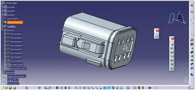
3D Data of connector is downloaded from the given reference and image of the same is shown below
2. Create required geometrical properties
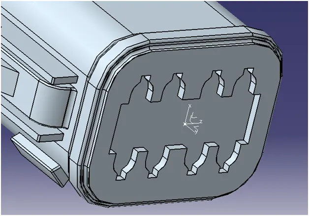
Geometric Parameters used to define the connector are points and coordinate system (axis). Point must be defined exactly on the middle of the connecting face. Axis system should be defined such that
- Z-axis should be pointing across the connector from left to right
- Y-axis should be pointing towards the front face of the connector
- X-axis should be pointing in the direction towards the locking mechanism of the clip
3. Define part as connector
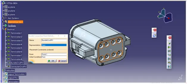
4. Define ‘Bundle connection point’
This point defines where the harness bundle segment point will end when routed to the electrical connector. The point should lie exactly middle of the connection face as shown in image.
5. Define ‘Connector connection point’
This point is used for the connection of one connector to another connector.
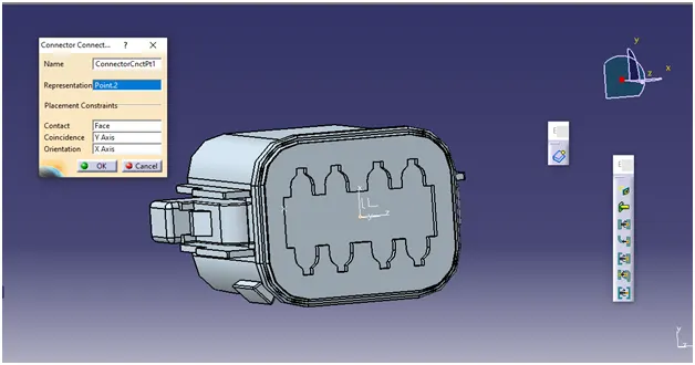
6. Define ‘Cavity connection point’
This point is used to define the connection of a connector to a connector clip. This applies only to those connectors which have the mounting feature for a connector clip. Since this connector had no mounting feature, there will not be any cavity connection point.
Similarly another connector is defined and image is shown below
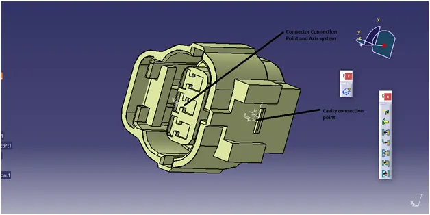
Defining mounting clip
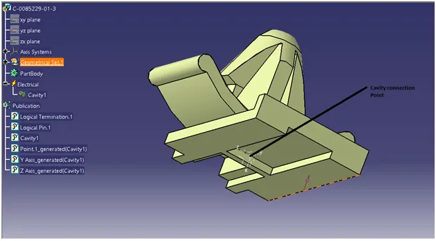
- First mounting clip is defined using ‘Defining Mounting Feature’ command
- Next ‘Cavity connection point’ is defined and shown in the image below.
Making assembly of Connector 2 and Mounting clip
- Open the ‘Electrical assembly design’ work bench
- Import the completely defined ‘connector 2’ and ‘mounting clip’ into the workbench
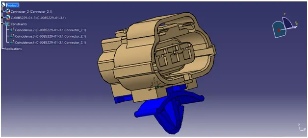
- Assemble the two components – ‘Cavity connection point’ is used to establish the coincidence constraint between the two parts.
- Completely assembly is shown in the image below.
Defining the Parts into catalogue
- Under ‘File’ dropdown menu select the ‘New’ – ‘Catalogue document’
- Add family –Give proper name under ‘Family Definition’.
- Select ‘Type’ as ‘Standard’.
- Save the catalogue
Conclusion
- All the required parameters are defined for the given connectors and mounting clip
- An assembly of connector and mounting clip is created
- Defined parts are added into the catalogue