Wiring harness design in CATIA V5 - 3D modeling Week 2 Challlenge
Aim:
To define the given connectors into electrically in CATIA V5 for the given connectors.
Given data:
- Deutsch DT06 – 08SA ( https://www.te.com/usa-en/product-DT06-08SA.html)
- Tyco 174357-2 (https://www.te.com/usa-en/product-2-174357-2.html?source=header-match)
- Tyco 85229-1 – (https://www.te.com/usa-en/product-85229-1.html?q=85229&source=header)
Steps followed:
Connector 3D:
Product code – Deutsch DT06 – 08SA
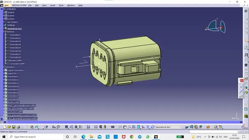
Step 1 – Downloaded the connector cad file from the te.com website.
Step 2 – Geometrical parameters
- Select part design
- Created point at bundle entry side and connector connection side.
- Created axis system at connector connection side.
- X – axis towards the locking mechanism
- Y – axis towards the front face of the connector
- Z – axis across the connector from left to right.
Step 3 – Define part as a connector.
- Switch to electrical part design.
- Select the define connector command.
- Select the geometry.
- Type = single
- No of terminations = 8
Step 4 – Define bundle connection point.
- Switch to electrical part design.
- Select bundle connection point command.
- Select the geometry.
- Name = we can rename it or keep default.
- Representation – select the bundle entry face of connector.
- Point – select the point that we created at bundle entry side.
- Initial condition – select the bundle entry face of connector.
Step 5 – Define connector connection point.
- Switch to electrical part design.
- Select the connector connection point command.
- Select the geometry.
- Name – keep default or rename it.
- Representation – Select the point that we created at connector connection side.
- Contact – select the front face of mating face of connector.
- Coincidence – select x – axis.
- Orientation – select y – axis.
Create Catalogue:
- Select file > new > catalogue document > add family > Name – connector > Type – Connector.
Adding created part file into catalogue:
- Open the Connector part file
- Switch to electrical part design.
- Select store device
- Catalogue – select the connector catalogue which is saved already in the device.
- Family – connectors.
Product code – Tyco 174357-2:
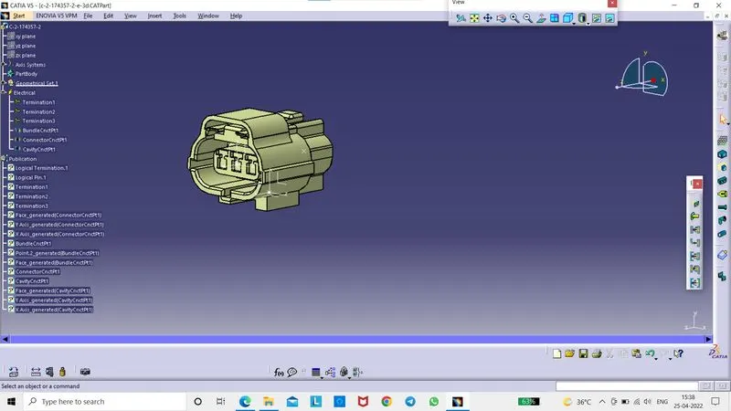
Step 1 – Downloaded 3D cad file of Tyco 174357-2 in te.com website.
Step 2 – Geometrical parameters.
- Switch to part design
- Created point at bundle entry side and connector connection side and also bottom edge of the connector.
- Created axis system at connector connection side and at bottom edge of connector for cavity connection point
- X – axis towards the locking mechanism
- Y – axis towards the front face of the connector
- Z – axis across the connector from left to right.
Step 3 – Define part as a connector.
- Switch to electrical part design.
- Select the define connector command.
- Select the geometry.
- Type = single
- No of terminations = 3
Step 4 – Define bundle connection point.
- Switch to electrical part design.
- Select bundle connection point command.
- Select the geometry.
- Name = we can rename it or keep default.
- Representation – select the bundle entry face of connector.
- Point – select the point that we created at bundle entry side.
- Initial condition – select the bundle entry face of connector.
Step 5 – Define connector connection point.
- Switch to electrical part design.
- Select the connector connection point command.
- Select the geometry.
- Name – keep default or rename it.
- Representation – Select the point that we created at connector connection side.
- Contact – select the front face of mating face of connector.
- Coincidence – select x – axis.
- Orientation – select y – axis.
Step 6 – cavity connection point.
- Switch to electrical part design.
- Select cavity connection point command.
- Name – keep default or rename it.
- Representation – select the point that we created at the bottom edge of connector.
- Contact – select the flat face at the bottom of connector.
- Coincidence – select x – axis.
- Orientation – select y – axis.
Add the file into catalogue:
- Switch to electrical part design.
- Select store device.
- Catalogue – select the connector catalogue that we already created and saved in the device.
- Family – Connector.
Product code – Tyco 85229-1:
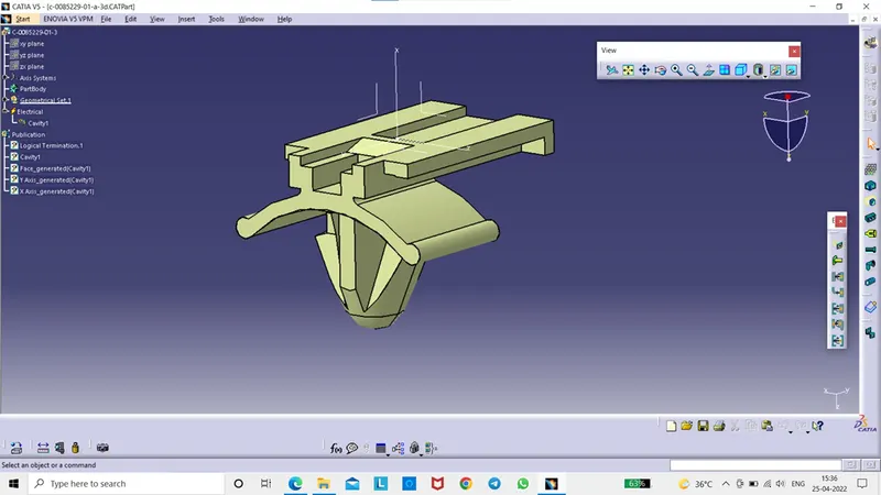
Step 1 – downloaded the cad file of Tyco 85229-1 in te.com website.
Step 2 – Geometrical parameters.
- Switch to part design.
- Created point at the top edge of locking mechanism of the mounting clip.
- Created axis system at the point that we created at the top edge of locking mechanism of the mounting clip.
- X – axis towards the locking mechanism of the mounting clip
- Y – axis toward the mating side with the connector.
- Z – axis towards the left or right side of the mounting clip.
Step 3 – Define mounting component.
- Switch to electrical part design.
- Select the define mounting component command.
- Select the mounting clip geometry.
- Select OK.
Step 4 – Define cavity point
- Switch to electrical part design.
- Select the define cavity command.
- Select the geometry.
- Name – keep default or make changes.
- Representation – select the point that we created at the top edge of the locking mechanism of the mounting clip.
- Contact – select the face that is going to be mated with the connector.
- Coincidence – select the x – axis.
- Orientation – select the y – axis.
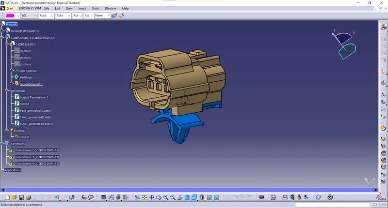
Assembly of connector Product code – Tyco 174357-2
And mounting clip Product code – Tyco 85229-1
- Open electrical assembly design part file.
- Copy and paste the connector part file and mounting part file in it.
- Select the connect electrical devices.
- Select the mounting clip and connector. Now it is connected