Radar Mast & Final Assembly of Yacht
Objective:
The main objective of this project is:
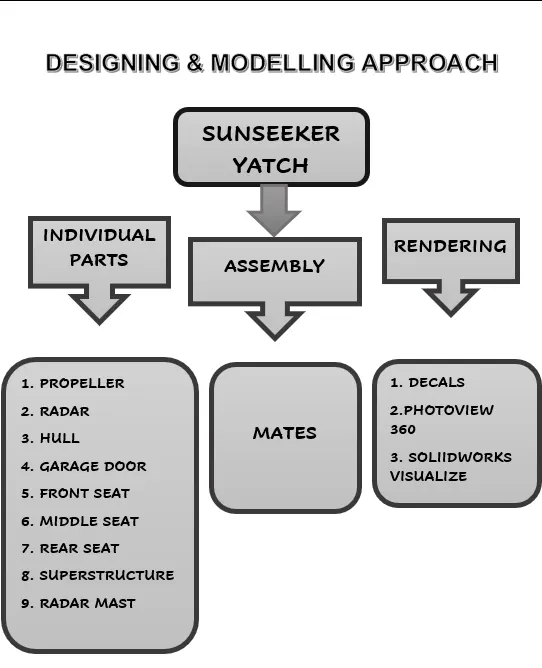
- To create the individual parts of sunseeker predator yacht in solid works.
- To assemble all the individual parts to get the complete model of Yatch.
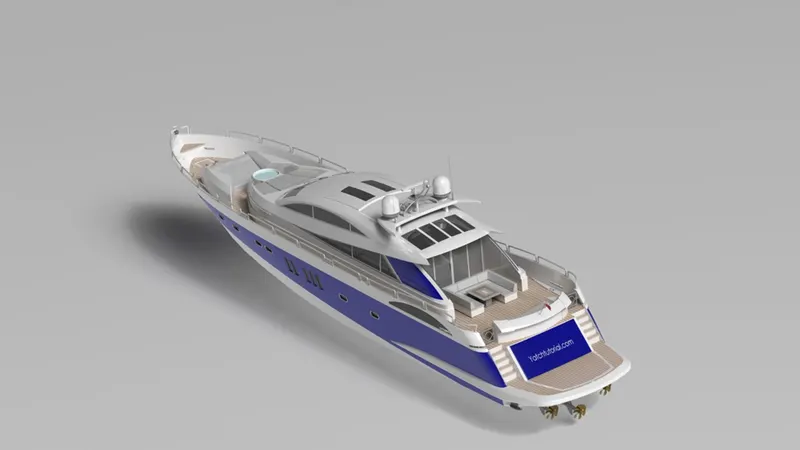
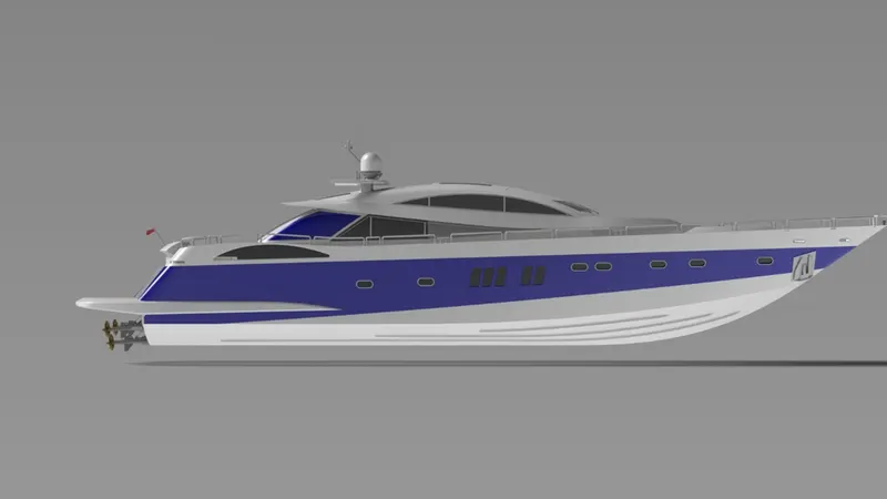
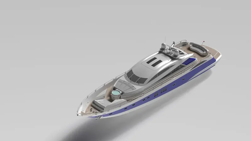
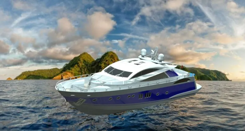
- To create the photorealistic model of Yatch by rendering it in photo view 360 and Solid works Visualize.
Introduction:
A yacht is basically a watercraft which is mainly used for pleasure, cruising or racing. Nowadays, yachts are mostly used for leisure. Until 1950’s, all the yachts are made up of wood, iron and steel. But nowadays, very wide range of materials were used for building the yacht. Yachts are using for commercial and own purpose. Commercial yachts may carry no more than 12 passengers and private yachts are solely used for pleasure of the owner. Even though, wood is still used for construction of hull, but the fiber glass material is the most common material which is used for construction of hull followed by aluminum, steel and carbon fiber. Apart from these materials like carbon fiber and aramid fiber, spruce veneers laminated with the epoxy resins have the best weight to strength ratios of all the boat building materials.
Depending on a size, a cruising yacht have at least two cabins which is a main salon and a forward starter room. And yachts have a communication equipment, instrumentation and navigation electronics.
Communication equipment’s are like radios in a variety of bandwidths and instrumentation like depth sounder, anemometer and compass which provides the information such as depth of water under the vessel, windspeed and directional orientation. And also have the navigation electronics like gps, chart plotter and radar which is used to identify the vessel’s location by gps, and radar is used to identify the nearby shore.
Tools and features used while designing the yacht:
The various features used for modelling and assembling the American chopper to be discussed below.
Extrude:
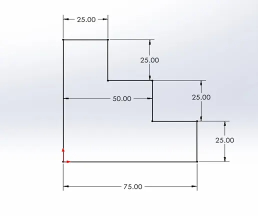
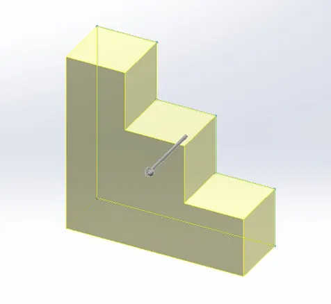
- An extrude feature is used to convert the 2D sketch of an enclosed area into the 3D model by specifying the direction and dimension of the component.
- Objects can be extruded orthogonally from the plane of the source object, in a specific direction or along a selected path.
2D sketch and 3D model:
Revolve:
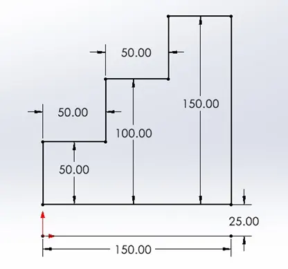
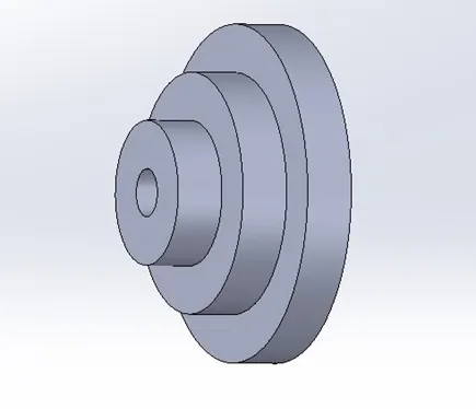
- Revolve feature is used to create a revolved object of 2D geometry into 3D object with the reference of axis or a centerline by specifying the direction and dimensions of the object.
- This feature is used for creating a circular form of objects like pipes, shafts.
- We can use this revolve feature to create a solid, surface or a thin object.
2D sketch:
3D Model:
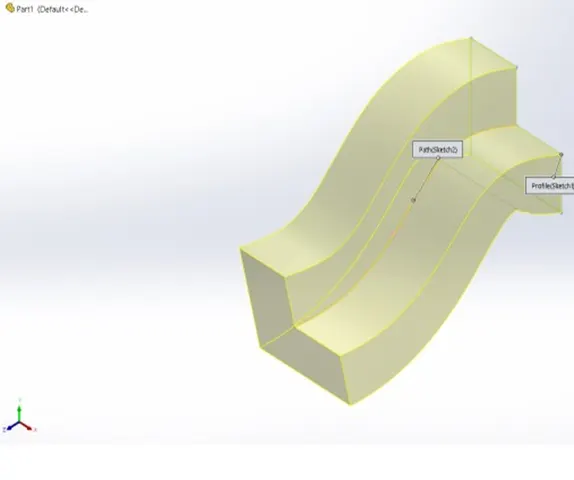
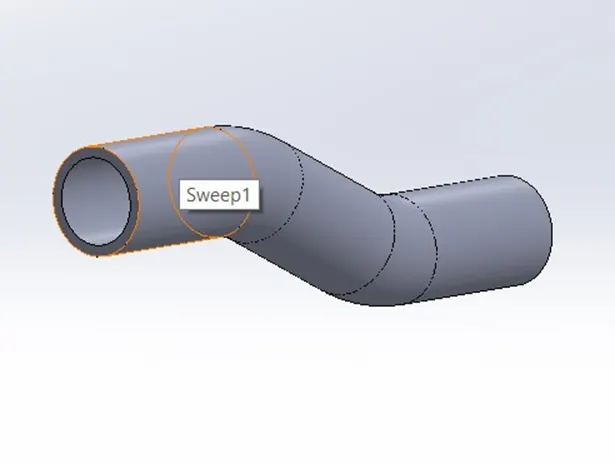
Sweep:
- A sweep feature is used to create a swept object of 2D sketch along an open or closed path.
- This feature is used for creating both the solid and surface sweep objects.
- A closed loop and path are required to create a swept object.
3D Object:
Lofted Boss:
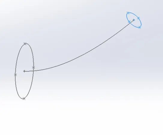
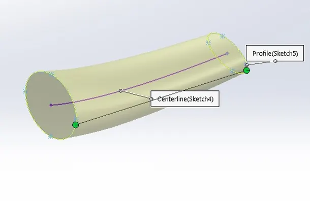
- Loft Boss or Base tool is also a similar tool like Extrude boss, revolved boss, Sweep boss, etc.
- This loft tool is mainly used to create a material (solid or surface) between two or more profiles.
2D Sketch:
3D Model:
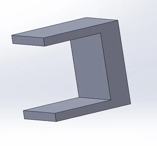
Extruded cut:
- Extruded cut feature is used to remove a material from solid object.
- This feature can be used to create a cut or remove a material in both the open and closed objects.
- Extruded can be performed in a model by sketching the two-dimensional cross section of the cut directly on the plane of the part
- We can remove the material throughout the object or up to next of the model in specified direction.
3D Model:
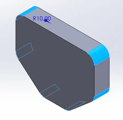
Fillet:
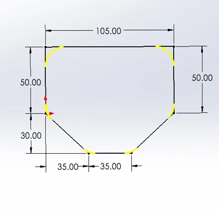
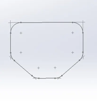
- A fillet is an arc that is created a tangent between two 2D objects.
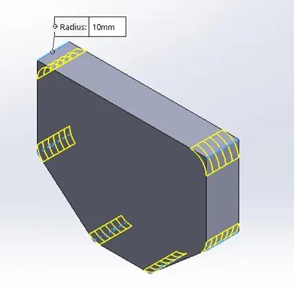
- A fillet tool is used to create a smooth rounded edges of an object in 2D geometry and also in 3D model in both internal and external face of an object by specifying the radius.
- We can do fillet for all the edges of a face, selected set of faces, selected edges, or edge loops.
2D Sketch Fillet:
3D Filleted Objects:
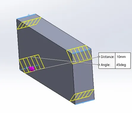
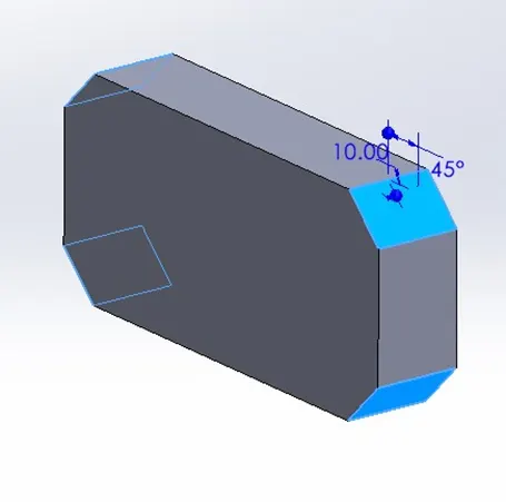
Chamfer:
- Chamfer tool is used to create a tapered edge of an object by removing the sharp edges.
- Chamfer is created by giving the distance and angle to get a tapered edge.
- This feature is used in woodworking, glass cutting, etc.
3D Object:
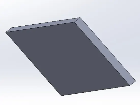
Mirror:
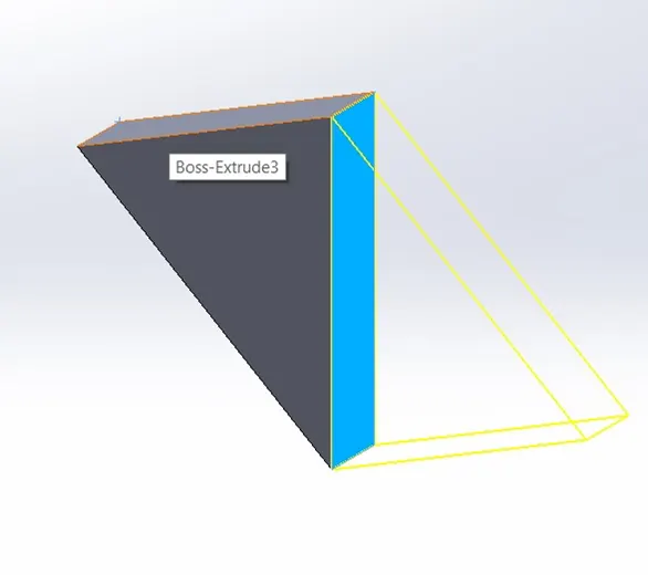
- Mirror tool in solid works is used to create an opposite hand version of a 2D sketch or 3D object based on a reference line or a plane.
- This feature is mainly used to save the time by creating half of the geometry and then mirror it to get completed sketch.
- We can also delete the original object by keeping the mirrored object or we should keep both original and mirrored objects.
3D Mirrored Object:
Shell:
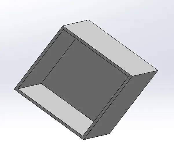
- Shell command is used to create a hollow part in a solid object.
- It removes the material inside the object by keeping the thin or thick edges of the component.
- We can see this hollow part in a solid object by using the sectional view.
3D Object:
Types of patterns:
There are various types patterns used in solid works. We are going to discuss in detail for the following patterns.
- Linear pattern.
- Circular pattern.
- Curve driven pattern.
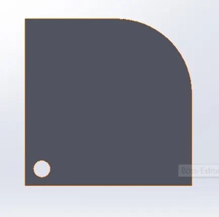
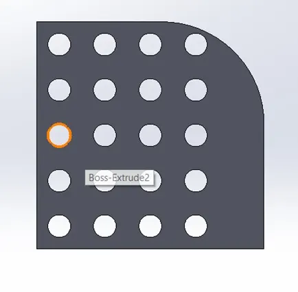
Linear pattern:
- Linear pattern is used to create multiple instances of one or more features than can be spaced uniformly along a path in a linear direction.
- This feature is used to drive the features one after one with uniform distance
Example:
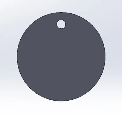
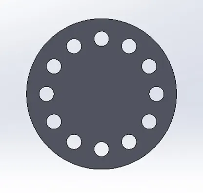
Circular pattern:
- Circular pattern is used to create multiple instances of one or more feature that you can space uniformly around an axis.
- For this circular pattern, we need to specify the axis of revolution, the total revolution angle and number of instances required.
Example:
Curve Driven Pattern:
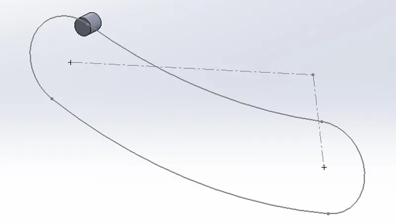
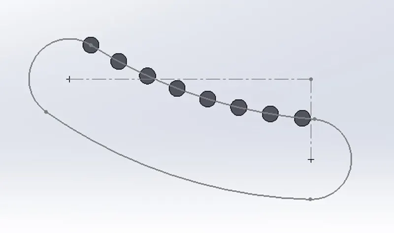
- Curve driven pattern is used to create multiple instances of a feature, face or a body that following through the curve.
Example:
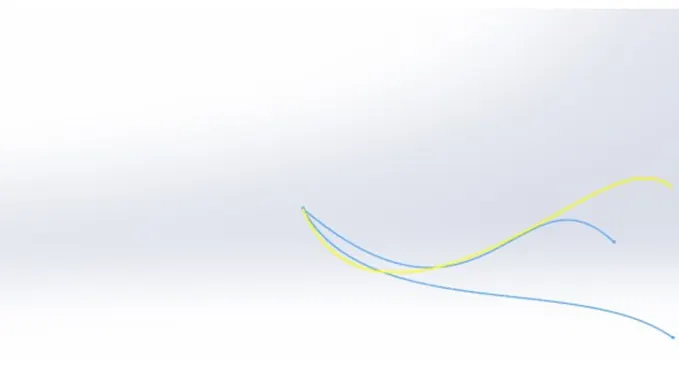
Projected curve:
- A projected curve is a 3D curve that represents the intersection of two extruded surfaces of two sketches on intersecting planes.
Mates:
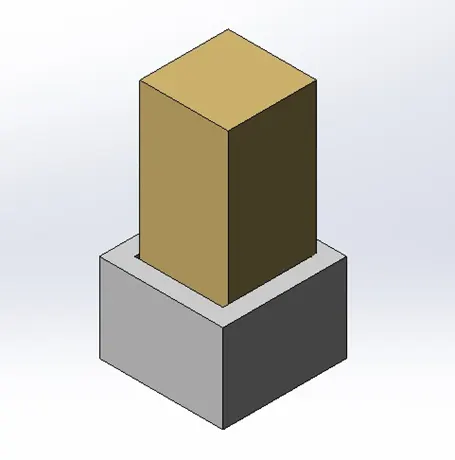
- Basically, mate feature is used for assembling the individual parts to get a complete model by giving the relations between the two individual faces such as coincident, tangent, perpendicular, parallel, concentric etc.
- The mate can be done between two faces by specifying the distance or an angle between them. In this below image we did a coincident mate.

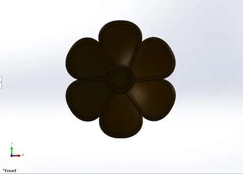
Propeller:
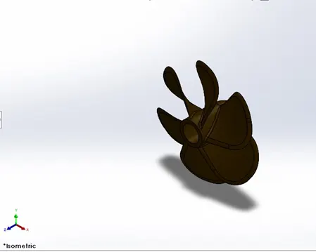
A propeller is used to propel the yacht by using the power generated and transmitted to it by the engine through the drive shaft which is connected to the propeller and engine. The transmitted power is converted from rotational motion to generate a thrust which imparts momentum to the water, resulting in a force that acts on the yacht and pushes it forward.
Marine propellers are made from corrosion resistance materials like an alloy of aluminium and stainless steel, alloy of nickel, alloy of bronze and other materials which have light weight and higher strength. Because they are directly in contact with the sea water
Tools and features used:
- Sketch
- Revolved boss
- Lofted boss
- Fillet
- Extruded cut
- Circular pattern
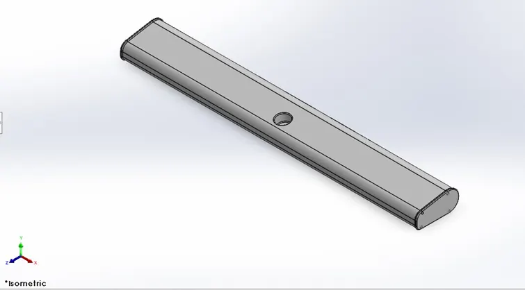
Radar:
A Radar is a navigation electronic device used in marines to detect and identify the ships and obstacles at which distance to avoid the collision between them and to navigate the vessel from one point to another point safely. The marine radar is classified under the X-band and S-band frequencies. The X-band radar is a higher frequency radar which is used for a sharper image and better resolution whereas the S-band radars are used especially in rain and fog for identification and tracking. With the help of the radar, accidents are prevented at the sea. The ship radar has a screen (referred to as the Plan Position Indicator) that displays all the targets that are present within the radar range. Since all the objects are clearly visible on the screen, navigating and monitoring the position of the ship becomes really feasible.
Tools and features used:
- Sketch
- Offset entities
- Convert entities
- Extruded boss
- Fillet
- Extruded cut
- Sketch driven pattern
- Mirror
- Split line
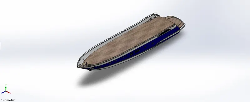
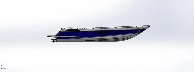
Hull:
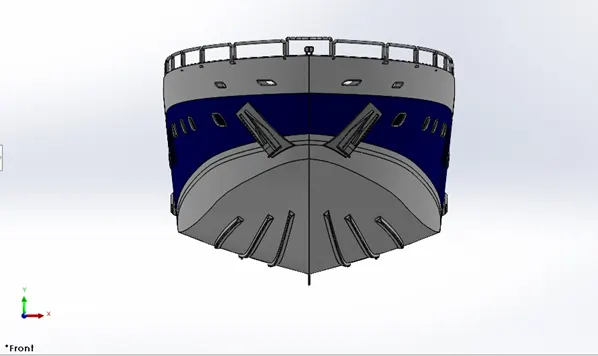
A hull is a watertight body of a ship or boat. The hull may open at the top or it may be fully or partially covered with a deck. A top of the deck is a deckhouse and other superstructures such as funnel, derrick, or mast. The line where the hull meets the water surface is called the waterline. There are four types of hulls. They are Flat-Bottom hulls, Round-Bottom hulls, V-shaped hulls and multi-Hulled.
The type of hull chooses based upon several factors considering such as cost, hydrostatic considerations (accommodation, load carrying and stability), hydrodynamics (speed, power, motion and behavior in a sea) and other some considerations according to the ship’s role. The hull design needs to be precise curvature during the sketching stage to avoid any bad geometry for showing up in a modelling stage.
Tools and features used:
- Sketch
- Offset entities
- Projective curve
- Lofted surface
- Trim surface
- Extruded surface
- Knit surface
- Fill surface
- Shell
- Extruded boss
- Extruded cut
- Fillet
- Chamfer
- Swept boss
- Revolved boss
- Dome
- Helix/spiral
- Linear pattern
- Delete face
- 3D sketch
- Mirror
- Spilt body
- Split line
- Offset surface
Garage door:
Garage door body was splitted from the hull part and imported it separately for modelling and saved as a separate part. The garage door was mated with the hull during assembly.
Tools and features used:
- Sketch
- Extruded cut
- Shell
- Fillet
- Mirror
Front seat:
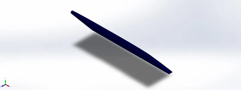
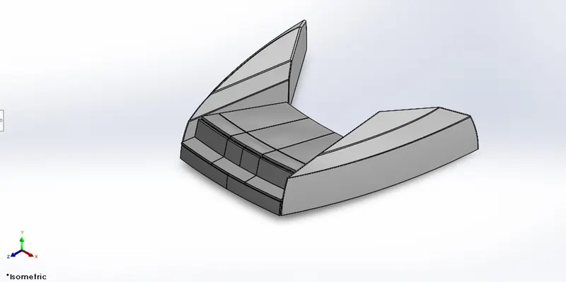
Front seat was placed in the front of superstructure on the hull by using the coincident mates with the hull in the assembly. The front seat was designed after importing the deck surface of hull as an interface surface.
Tools and features used:
- Sketch
- Offset entities
- Swept surface
- Extruded surface
- Trim surface
- Fill surface
- Lofted surface
- Knit surface
- Chamfer
- Fillet
- Revolved boss
- Extruded cut
- Mirror
- Dome
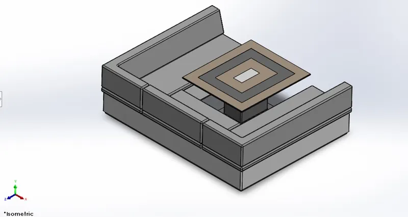
Middle seat:
The middle seat was placed in back portion of the hull and the area which is closely behind the back door of superstructure. The middle seat is placed in hull by using the coincident mates with the hull. It was designed after importing the deck surface of hull as an interface surface. The middle seat was designed by using the solid modelling commands which are used for modelling the front seat and rear seat
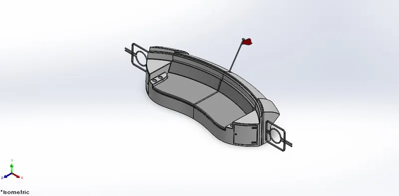
Rear seat:
The rear seat was placed on the back portion of hull over the garage behind the superstructure. It was placed on hull by using the distance mate and coincident mates with the hull. The rear seat was designed after importing the deck surface of the Hull as an interface surface.
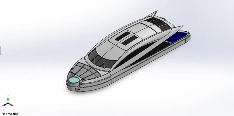
Superstructure:
The superstructure is an upward extension of an existing structure above the base line. It consists of the parts of ship or yacht that project above the main deck. The size of a watercraft’s superstructure can have many implications in its performance since these structures can alter their structural rigidity, their displacements and stability. It encloses the cabin and have a living area of the ship or yacht. They are designed in a manner, so that, they add value and hinder the speed and mobility in the least. It was designed after importing the deck surface of the hull as an interface surface. The modelling of superstructure requires precise curvature during the sketching stage to avoid any bad geometry from showing up in the modelling stage.
Tools and features used:
- Sketch
- Offset entities
- Convert entities
- Extrude surface
- Swept surface
- Knit surface
- Fillet
- Chamfer
- Ruled surface
- Trim surface
- Projected curve
- Lofted surface
- Surface fill
- 3D sketch
- Extend surface
- Delete face
- Extruded boss
- Extruded cut
- Offset surface
- Thicken surface
- Dome
- Swept boss
- Split line
- Mirror
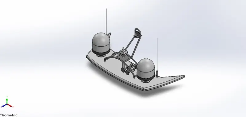
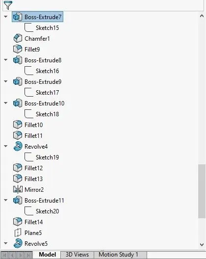
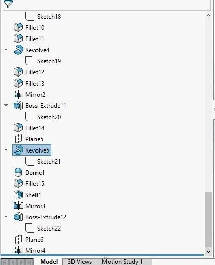
Radar Mast:
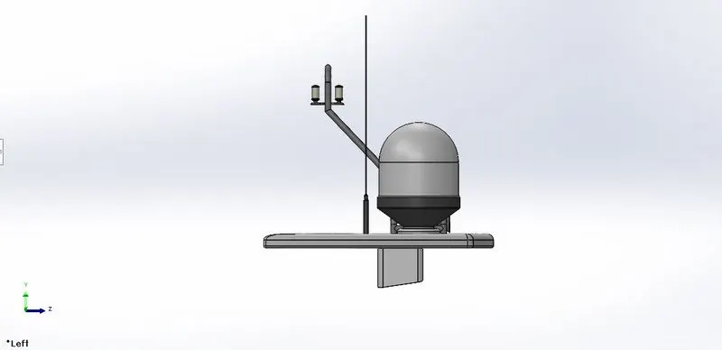
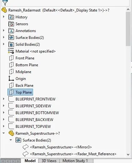
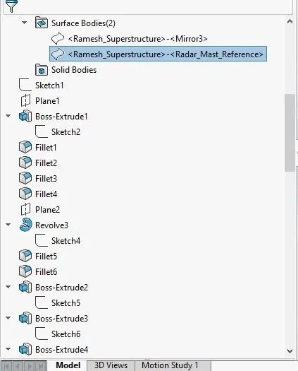
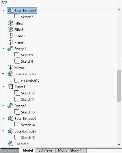
Radar Mast holds the radar, antennas, satellite domes and lights. It was designed after importing the top surface of the superstructure as a interface surface.
Tools and features used:
- Sketch
- Offset entities
- Extrude boss
- Fillet
- Revolved boss
- Swept boss
- Mirror
- Projected curve
- Chamfer
- Dome

ASSEMBLY OF YACHT:
The individual parts of yacht is assembled by using the required relations and mates such as coincident mate, concentric mate, distance mate.
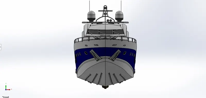
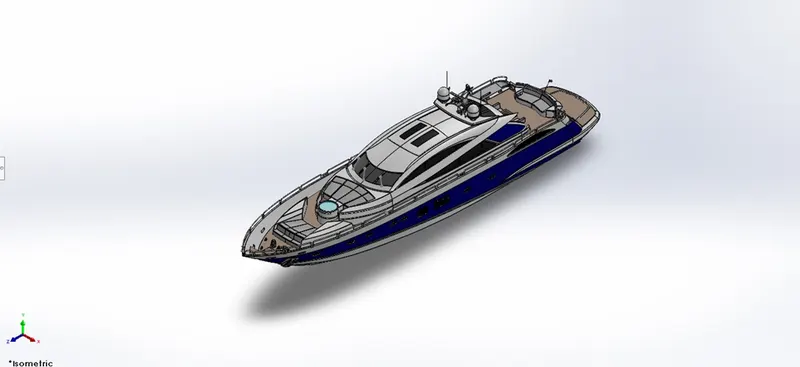
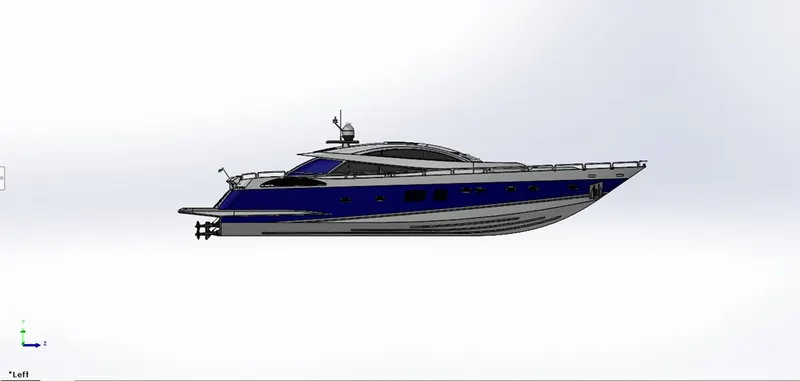
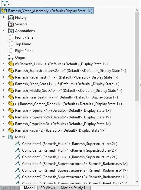
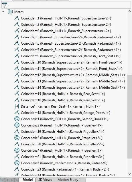
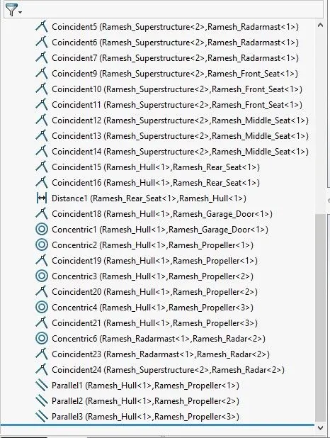
Photo view 360:
- Photo view 360 is a visualization and rendering solution includes with the solid works.
- It provides highly interactive environment for viewing designs as well as for creating photo-realistic rendering which is used to showcase our designs as well.
Rendering:
- Rendering is a process of creating realistic images of the photo realistic model with the environment.
- Rendering can be done by two ways in solid works.
- Photo view 360.
- Solid works visualize.
Rendering yacht using photo view 360 & solid works visualize: