Wiring harness routing & packaging Rules Week 3 Challenge
Objective:
- To define the mechanical components into electrically and prepare the catalogue for the sam as per the given data.
- To prepare the COT tubes and make the catalogue for the same.
Define the mechanical components into electrically and prepare the catalogue for them:
Steps followed:
P CLAMP:
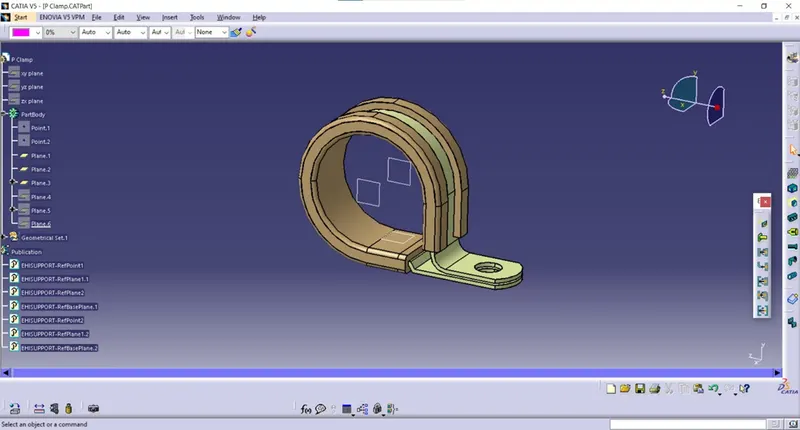
Step 1 – Downloaded the p clamp cad file from week 3 challenges.
Step 2 – Geometrical parameters
- Select part design
- Created point at left side of clamp (Entry side) and also created one more point at right side of the clamp (Exit side).
- Created planes such as entry plane (entry side), exit plane (exit side) and base plane (where the bundle needs to be touched to the surface of clamp)
Step 3 – Define part as support
- Switch to electrical part design.
- Select the define support part
- Select the geometry.
- Name – Keep default or rename it
- First plane definition:
Point – select the point at entry side
Plane – select the plane that we created at entry side.
- Second plane definition:
Point – select the point at exit side
Plane – select the plane that we created at exit side.
- Base plane definition: select the base plane that we are created.
Back shell:
Rectangular back shell:
Product code - 1738312-1
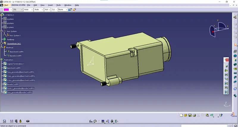
Step 1 – Downloaded 3D cad file of Tyco 1738312-1 te.com website
Step 2 – Geometrical parameters.
- Switch to part design
- Created point at back shell connection side and also at bundle connection side.
- Created axis system at back shell connection side.
- X – axis towards the left or right side
- Y – axis towards the back shell connection mating side
- Z – axis towards the top side of the back shell.
Step 3 – Define part as Back shell.
- Switch to electrical part design.
- Select the define back shell
- Select the geometry.
- Part number – keep default.
- Extra length – unset.
Step 4 – Define back shell connection point.
- Switch to electrical part design.
- Select back shell connection point command.
- Select the geometry.
- Name = keep default or rename it.
- Representation – select the back shell connection point.
- Contact – select the mating face of back shell.
- Coincidence – select the y – axis.
- Orientation – select the x – axis.
Step 5 – Define bundle connection point.
- Switch to electrical part design.
- Select the bundle connection point command.
- Select the geometry.
- Name – keep default or rename it.
- Representation – Select the bundle entry face of the back shell.
- Point – select the point that we created at bundle entry side of the back shell.
- Initial condition – select the bundle entry face of back shell.
Corrugated tubes:
Step 1 – create covering 3D part.
(For example – COT_20mm)
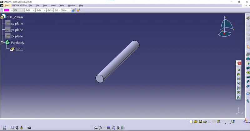
- Open new part file
- Switch to electrical part design.
- Select the define protection part command.
- Select the part or part body in the model tree.
- Name – rename according to the size of cot tube (COT_20mm)
- Type – corrugated tube.
- Inner diameter – 17mm.
- Inner section – keep default.
- Thickness – 1.5mm
- Bend radius – we need to give bend radius 1.5x than the outer diameter of the cot tube, here we will give 30mm.
- Linear mass – keep default
- Light geometry – enable.
Now the 20mm cot tube is created by giving the above parameters. And followed the same process for creating the cot tubes with different diameters such as 15mm, 35mm, 10mm and 5mm cot tubes by changing the values.
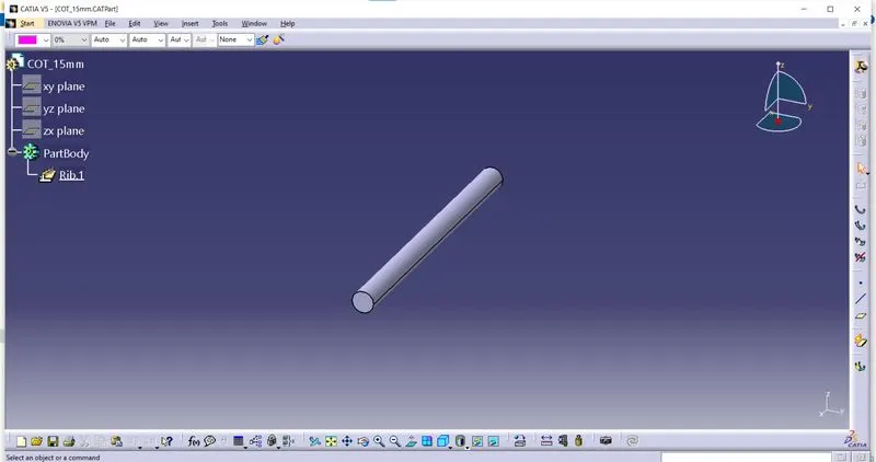
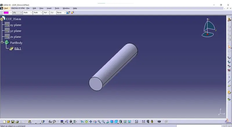
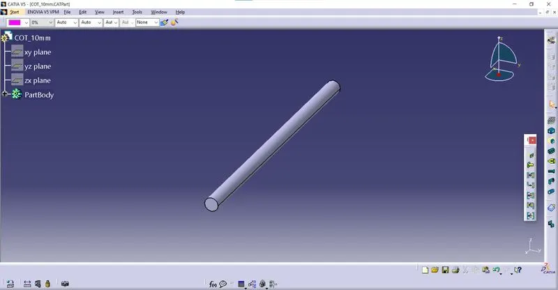
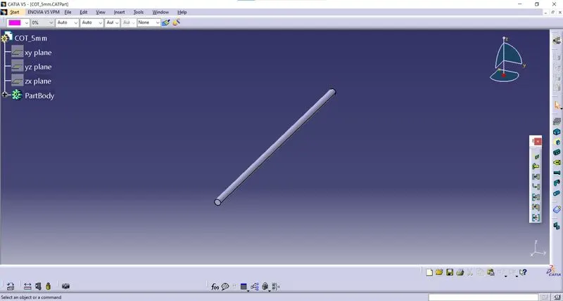
Create catalogue for cot tubes.
- File > new > select catalogue document > add family > Name – Cot tubes > Type – conduit.
Adding the part files into catalogue:
- Open the created cot tube part file.
- Switch to electrical part design.
- Select the store device.
- Select the cot tubes catalogue document that we already created and saved in the device.
- Family – select cot tubes.
- Select ok.