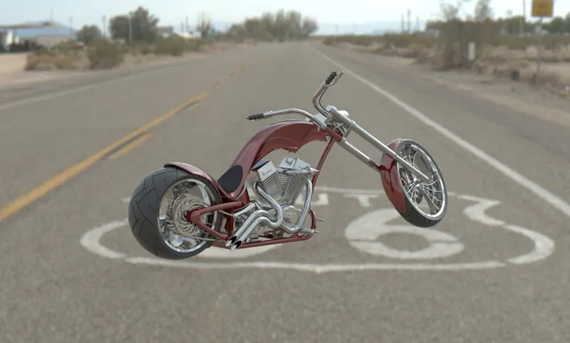
Assembly and Rendering of American Chopper using Solid works.
INTRODUCTION:
In this project, we learnt in detailed about designing the individual parts of the American chopper and assembling them to get a complete model of American chopper using Solid works. And it also explains the rendering of final model using Solid works Visualize to create more natural and realistic view of the Chopper.
OBJECTIVE:
The main objective of this project is:
- To learn how to create the individual parts of American chopper using 2D and 3D sketches in solid works
- To learn how to assemble all the individual parts to get the complete model of chopper.
- To learn how to apply the decals, applications of different of types of lights and setting up the camera.
- To learn how to create the photorealistic model of chopper and render it using photo view 360 and Solid works Visualize.
FEATURES USED TO MODEL AND ASSEMBLE THE CHOPPER:
The various features used for modelling and assembling the American chopper to be discussed below.
EXTRUDE:
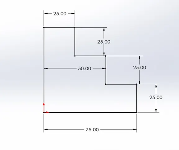
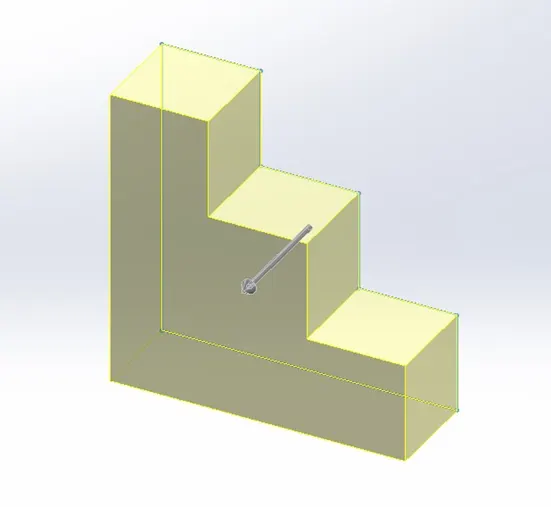
- An extrude feature is used to convert the 2D sketch of an enclosed area into the 3D model by specifying the direction and dimension of the component.
- Objects can be extruded orthogonally from the plane of the source object, in a specific direction or along a selected path.
2D SKETCH:
EXTRUDED INTO 3D:
REVOLVE:
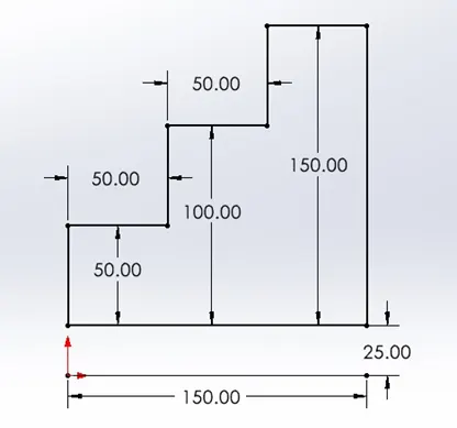
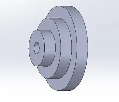
- Revolve feature is used to create a revolved object of 2D geometry into 3D object with the reference of axis or a centerline by specifying the direction and dimensions of the object.
- This feature is used for creating a circular form of objects like pipes, shafts.
- We can use this revolve feature to create a solid, surface or a thin object.
2D SKETCH:
3D MODEL:
SWEEP:
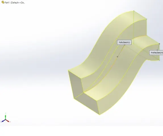
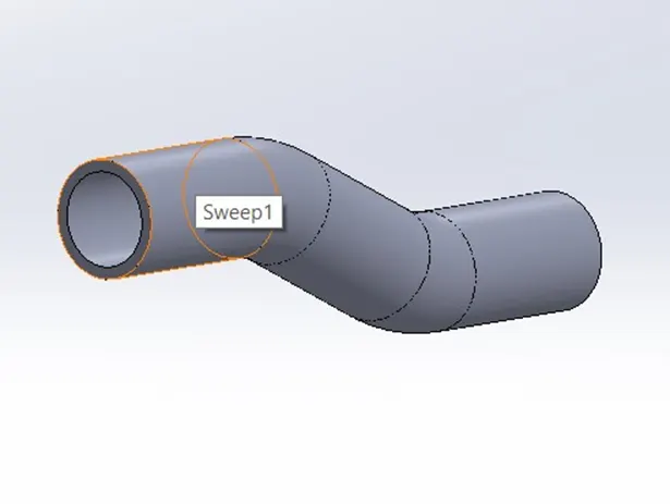
- A sweep feature is used to create a swept object of 2D sketch along an open or closed path.
- This feature is used for creating both the solid and surface sweep objects.
- A closed loop and path are required to create a swept object.
3D OBJECT:
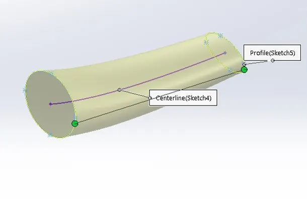
LOFTED BOSS/BASE:
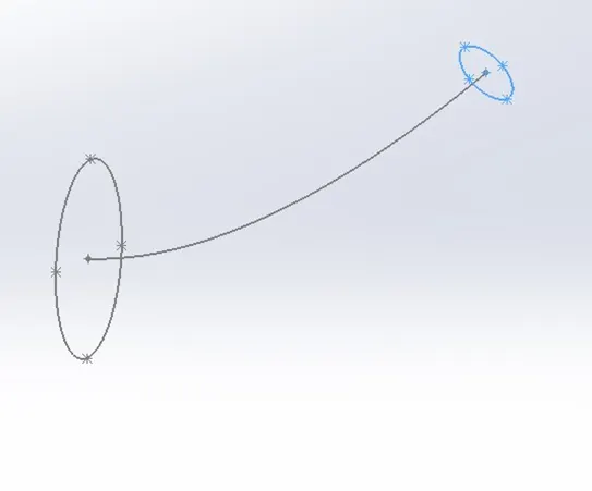
- Loft Boss or Base tool is also a similar tool like Extrude boss, revolved boss, Sweep boss, etc.
- This loft tool is mainly used to create a material (solid or surface) between two or more profiles.
2D SKETCH:
3D OBJECT:
EXTRUDED CUT:
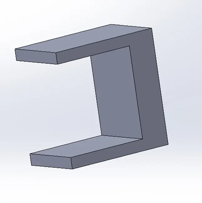
- Extruded cut feature is used to remove a material from solid object.
- This feature can be used to create a cut or remove a material in both the open and closed objects.
- Extruded can be performed in a model by sketching the two-dimensional cross section of the cut directly on the plane of the part
- We can remove the material throughout the object or up to next of the model in specified direction.
3D OBJECT:
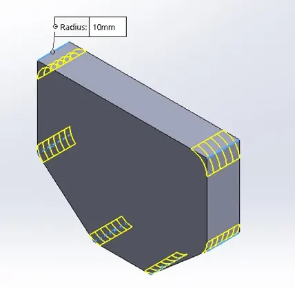
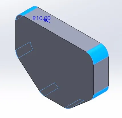
FILLET:
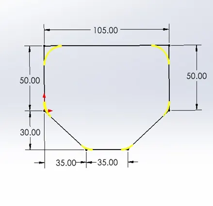
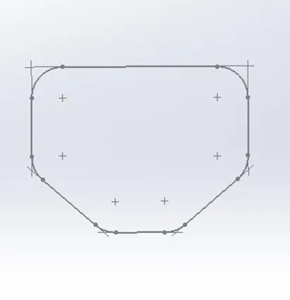
- A fillet is an arc that is created a tangent between two 2D objects.
- A fillet tool is used to create a smooth rounded edges of an object in 2D geometry and also in 3D model in both internal and external face of an object by specifying the radius.
- We can do fillet for all the edges of a face, selected set of faces, selected edges, or edge loops.
2D SKETCH FILLET:
3D FILLETED OBJECTS:
CHAMFER:
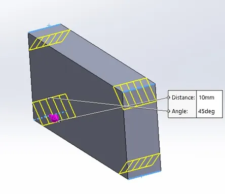
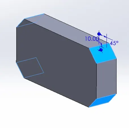
- Chamfer tool is used to create a tapered edge of an object by removing the sharp edges.
- Chamfer is created by giving the distance and angle to get a tapered edge.
- This feature is used in woodworking, glass cutting, etc.
3D OBJECT:
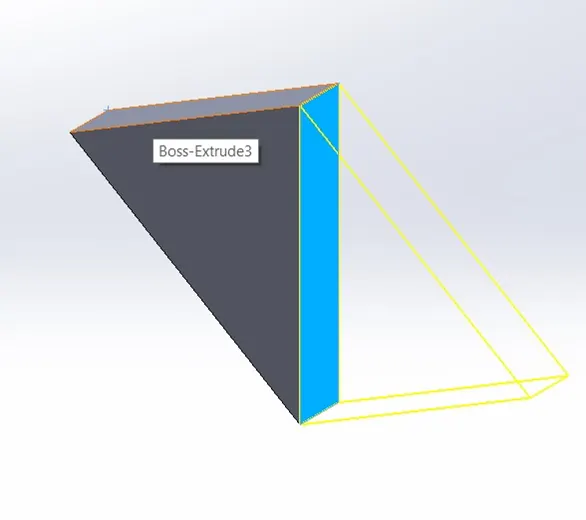
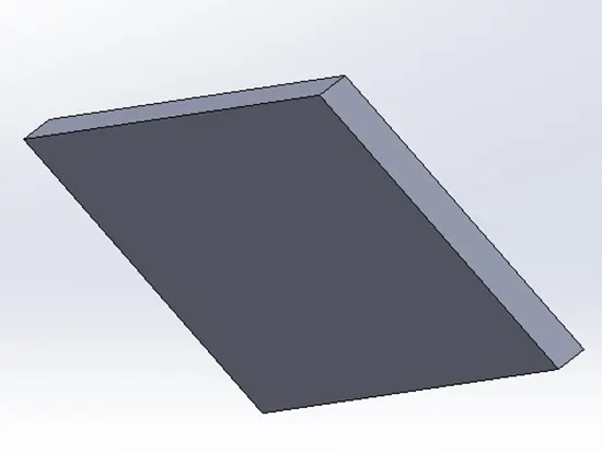
MIRROR:
- Mirror tool in solid works is used to create an opposite hand version of a 2D sketch or 3D object based on a reference line or a plane.
- This feature is mainly used to save the time by creating half of the geometry and then mirror it to get completed sketch.
- We can also delete the original object by keeping the mirrored object or we should keep both original and mirrored objects.
3D MIRRORED OBJECT:
SHELL:
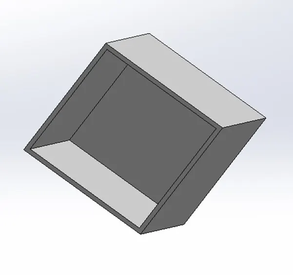
- Shell command is used to create a hollow part in a solid object.
- It removes the material inside the object by keeping the thin or thick edges of the component.
- We can see this hollow part in a solid object by using the sectional view.
3D OBJECT:
TYPES OF PATTERNS:
There are various types patterns used in solid works. We are going to discuss in detail for the following patterns.
- Linear pattern.
- Circular pattern.
- Curve driven pattern.
LINEAR PATTERN:
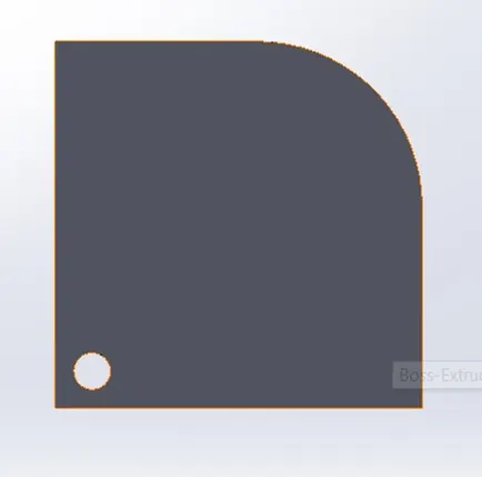
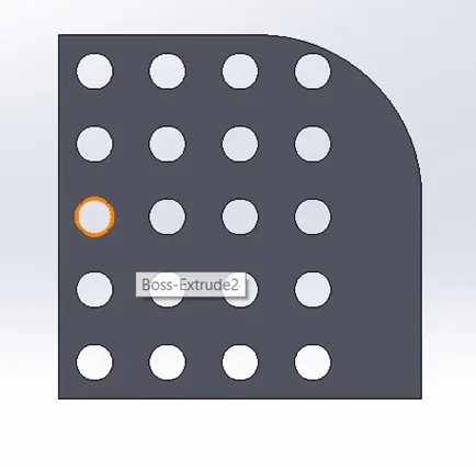
- Linear pattern is used to create multiple instances of one or more features than can be spaced uniformly along a path in a linear direction.
- This feature is used to drive the features one after one with uniform distance.
EXAMPLE:
CIRCULAR PATTERN:
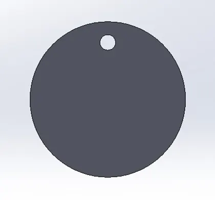
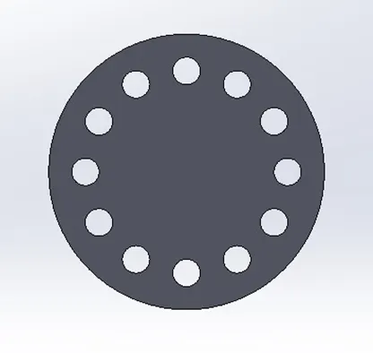
- Circular pattern is used to create multiple instances of one or more feature that you can space uniformly around an axis.
- For this circular pattern, we need to specify the axis of revolution, the total revolution angle and number of instances required.
EXAMPLE:
CURVE DRIVEN PATTERN:
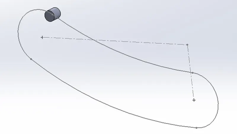
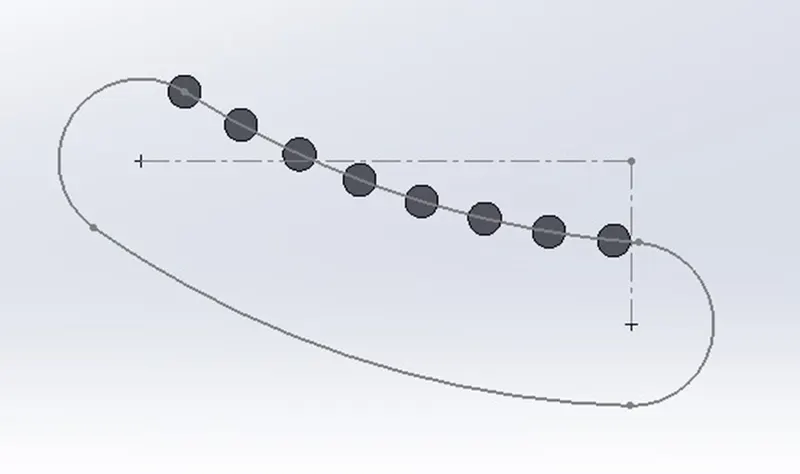
- Curve driven pattern is used to create multiple instances of a feature, face or a body that following through the curve.
EXAMPLE:
PROJECTED CURVE:
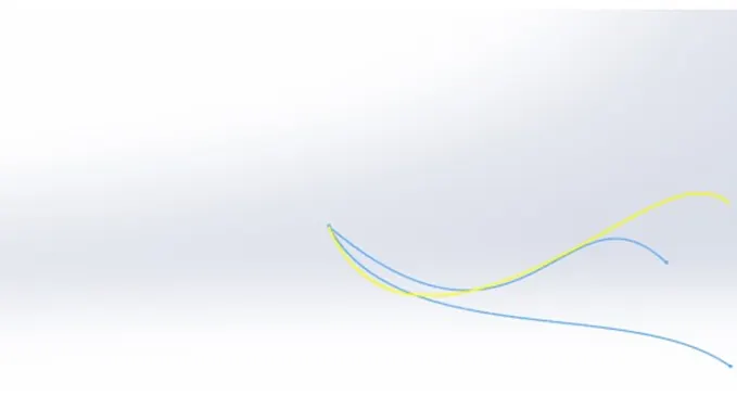
- A projected curve is a 3D curve that represents the intersection of two extruded surfaces of two sketches on intersecting planes.
MATES:
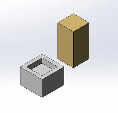
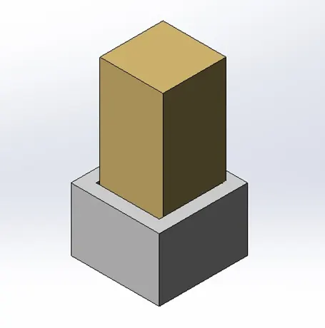
- Basically, mate feature is used for assembling the individual parts to get a complete model by giving the relations between the two individual faces such as coincident, tangent, perpendicular, parallel, concentric etc.
- The mate can be done between two faces by specifying the distance or an angle between them. In this below images we did a coincident mate.
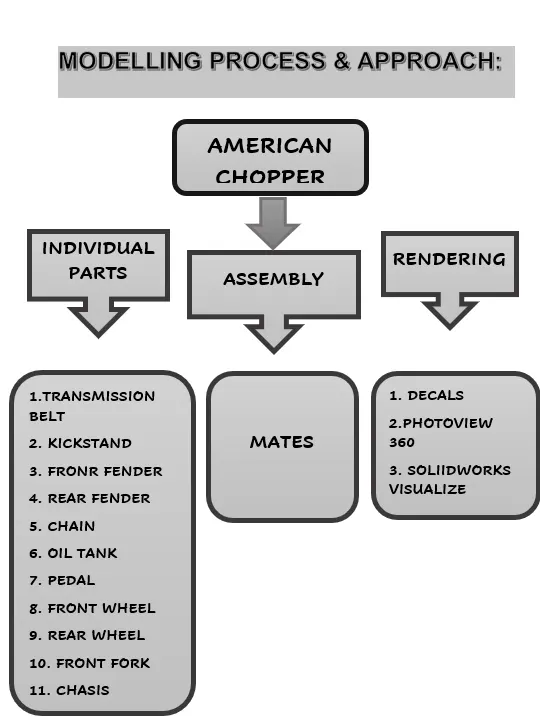
TRANSMISSION BELT:
- Transmission belts are mainly used for power transmission without any phase shift.
- It is a loop of flexible material which connects two or more rotating shafts mechanically for the power transmission.
- Belt drives are often cheaper than the equivalent gears and useful for transmitting power between shafts that are widely separated or nonparallel drives.
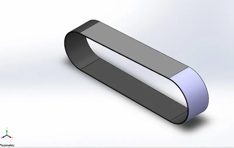
FEATURES USED FOR MODELLING TRANSMISSION BELT:
- Sketch
- Offset
- Extrude boss
- Fillet
- Appearances
PROCEDURE FOLLOWED TO MODEL THE TRANSMISSION BELT:
- Now open a new solid works part.
- Then select the front plane and start sketch.
- Now the 2D sketch in front plane is created by using commands such as line and arc. And offset command is also used to make a duplicate of the original sketch.
- Then the required dimensions and the relations are given to make the sketch fully defined and then exit the sketch.
- Then extrude the sketch using extrude boss/base feature to convert the 2D sketch into 3D model
- Now the fillets are applied to the model as per the given dimensions.
- Then applied the required appearance to the entire model.
- Finally, the model is saved as a “Transmission Belt”.
KICK STAND:
- Kickstand is also known as side stand which is used to support the chopper whenever it needs to be rest on the ground.
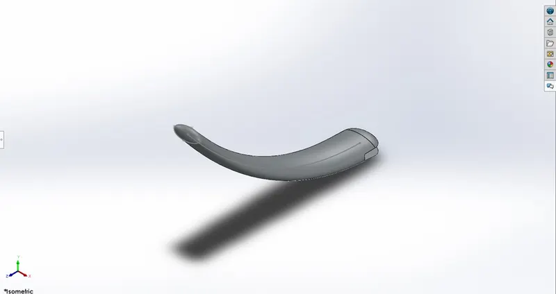
FEATURES USED TO MODELLING KICKSTAND:
- Sketch
- Loft
- Dome
- Extruded cut
- Extrude boss
- Fillet
- Split
PROCEDURE FOR MODELLING THE KICKSTAND:
- Now open the new solid works part.
- Before starting the sketch, rename the default planes as follows:
- Front plane – Front plane.
- Top plane – Top plane.
- Right plane – Midplane.
- Now select frontplane and start sketching on it
- Now the 2D sketch of kickstand is created in front plane by using the sketch tools. Here we also used the spline and trim commands while sketching.
- We also created a new plane for our requirement to draw the ellipse.
- Then the relations and dimensions are applied to make the sketch fully defined.
- Then the loft boss of kickstand is created by using the loft command.
- Then the dome feature is applied at both smaller and larger faces to make a smooth finish.
- Then extruded cut feature is used to make a cut by removing the unwanted material from the kickstand.
- Then the extruded boss is used to make a boss between the removed area at the larger face of kickstand.
- Fillets are applied at the sharper edges to make a smooth finish as per the required radius.
- Next, we applied the appearance to the kickstand.
- Finally, the part is saved as a “kickstand”.
FRONT FENDER:
- The front fender is mounted on the front fork above the wheel to protect the rider, chopper and other parts of chopper from the debris and foreign particles.
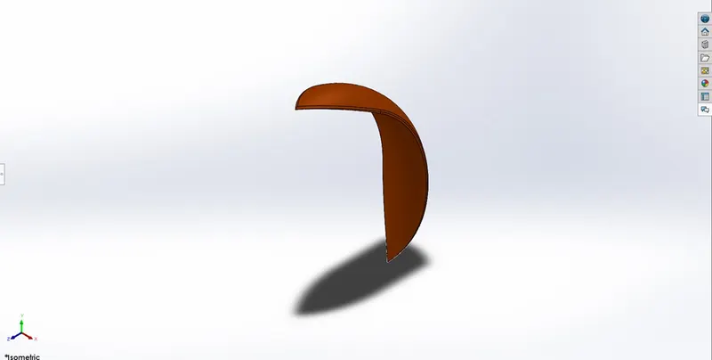
FEATURES USED TO MODEL THE FRONT FENDER:
- Sketch
- Offset entities
- Extend entities
- Trim entities
- Spline
- Dynamic mirror
- Revolve
- Split tool
PROCEDURE FOLLOWED TO MODEL THE FRONT FENDER:
- Now open the new solid works part.
- Before going to start the sketch, we need to rename the default planes as follow:
- Front plane – Vertical plane front fender.
- Top plane – Center plane front fender.
- Right plane – Midplane front fender.
- Now select the Vertical plane front fender and start sketching.
- The 2D sketch of the front fender is created by using the above planes and by using the sketch tools.
- We applied the relations and dimensions as per the requirement to make a sketch fully defined.
- We now created the fully defined 2D sketch and revolved the sketch by using revolved boss to make it into a 3D object.
- While sketching we also used offset command, trim entities and extend entities.
- Then we removed the unwanted material from the fender by using the spline and split tools.
- Fillets are applied at the sharper edges of fender to make a smooth and round finish.
- Next, we applied the required appearance to the model.
- Finally, the part is saved as a “Front Fender”.
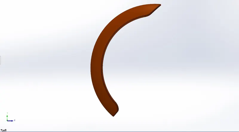
REAR FENDER:
- The purpose of the rear fender is similar as front fender. The rear fender is mounted on the chassis above the rear wheel.
FEATURES USED TO MODEL THE REAR FENDER:
- Sketch
- Offset entities
- Extend entities
- Trim entities
- Revolve boss
- Spline
- Split
- Appearances
PROCEDURE FOLLOWED FOR MODELLING THE REAR FENDER:
- Open a new solid works part
- Then rename the default planes into the following:
- Front plane – Vertical plane rear fender.
- Top plane – Center plane rear fender.
- Right plane – Midplane rear fender.
- Now start sketching on vertical plane rear fender.
- Then the 2D sketch is created by using different type of sketch tools. And also used some other tools like offset entities, extend entities and trim entities.
- Then the relations and dimensions are applied to the sketch to make it fully defined.
- Now by using revolved boss feature, we converted the 2D sketch into a 3D object.
- By using the split tool, we removed the unwanted material from the fender.
- Then the sharp edges are converted into smooth and rounded edges by using fillet tool.
- Then we applied the required appearance to the model.
- At last we saved the part as a “Rear Fender”.
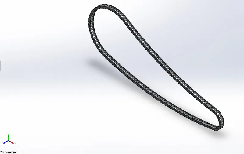
CHAIN:
- Chain is a type of transmission system which is used to transmit a power from the engine to the Rear wheel.
- The sprocket is used to transmit the power to the chain. The sprocket is connected with the shaft with the help of a key.
FEATURES USED TO MODEL THE CHAIN PART:
- Sketch
- Trim
- Blocks
- Extrude
- Curve driven pattern
- Fillets
- Appearances
PROCEDURE FOR MODELLING CHAIN:
- Open a new solid works part.
- Before creating geometry, rename the default planes as follow:
- Top plane – Center plane chain
- Front plane – Midplane chain
- Right plane – Front plane chain
- Now select Midplane chain and start sketching on it.
- We now created 2D sketch as a path of chain which is going to follow. And also created the sprocket of the chain.
- We applied the relations and dimensions to the sketch to make it fully defined.
- Now we created the sketch blocks using sketch tools and saved the sketch blocks in a separate folder. We can use this block simply by inserting it into the sketch whenever we required.
- Then extrude this block by inserting it in a sketch and use curve driven pattern to pattern it through the path.
- Then fillets are used to make a smooth edge of the objects.
- Apply the appearance to the entire model and save the part as a “Chain”.
Process to make blocks:
- Create a sketch.
- Click make block (Tool>Block>Make Block).
- Select the entity you want to make as a block for block entities.
- Click OK and save the first block.
- Repeat the steps 2-4 to make another block.
- With the sketch in edit mode, add the required relations.
- Finally save the part.
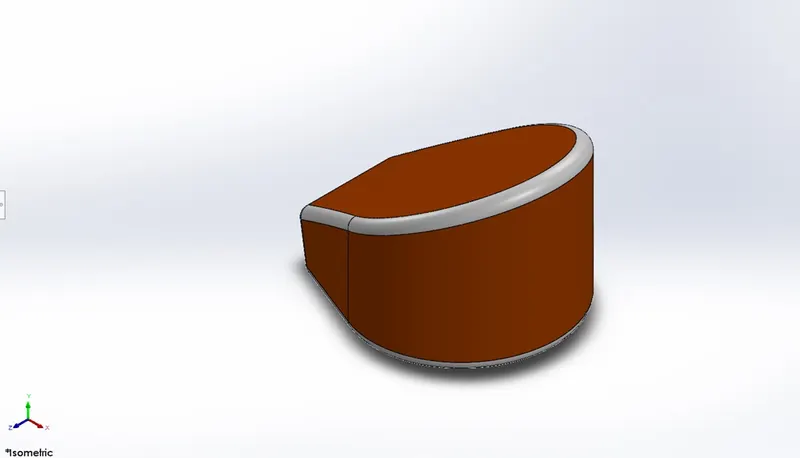
OIL TANK:
- Generally, Oil tank is used to store the fuel required to run the engine.
- It is a hollow tank. The thickness of the oil tank is 3mm in our chopper model.
FEATURES USED TO MODEL THE OIL TANK:
- Sketch
- Extrude boss
- Combine
- Fillet
- Shell
- Appearance
PROCEDURE USED FOR MODELLING THE OIL TANK:
- Open a new solid works part.
- Before creating any geometry, lets rename the default planes as follows planes:
- Front plane – Midplane oil tank.
- Top plane – Top plane oil tank.
- Right plane – Right plane oil tank.
- Now select top plane oil tank and start sketching.
- By using sketch tools, we created the 2D sketch of an oil tank.
- We also used dynamic mirror command and the spline command while sketching.
- Then apply the relations and dimensions to make the sketch fully defined.
- Then extrude the sketch using extrude boss. And then combine the extruded parts to make 3D model of oil tank.
- Then apply the fillet to the edges of the oil tank by specifying required radius.
- By using shell feature, we made a tank hollow by specifying the thickness of edges.
- Then we applied the appearance to the object. And saved the part as a “Oil tank”.
COMBINE:
- Combine feature is used to combine two bodies manually like add, subtract, etc.
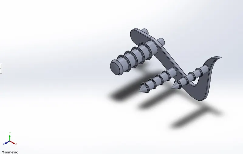
PEDAL:
- Pedal is an external part which is attached to the chassis. The pedal is used to place the foot on the top of it to give better comfort to the rider while riding the chopper.
FEATURES USED FOR MODELLING THE PEDAL:
- Sketch
- Extrude boss
- Revolve boss
- Offset
- Linear pattern
- Fillet
- Dome
- Chamfer
PROCEDURE FOLLOWED FOR MODELLING THE PEDAL:
- First of all, open a new solid works part.
- Here we are going to sketch on a default plane.
- Select Front plane and start sketching in it.
- Here we created the basic 2D sketch of the pedal by using the sketch tools, and some other commands like spline command and offset entities.
- Then apply the relations and dimensions as per the requirement to make the sketch fully defined.
- Then extrude the 2D sketch by using the extrude boss feature.
- And create the revolve object as per the requirement by using the revolve boss feature.
- Then pattern the object by using the linear pattern.
- Then apply the fillets and chamfer to the model at requires areas.
- Then apply the appearance to the model and save the model as a “Pedal”.
FRONT WHEEL:
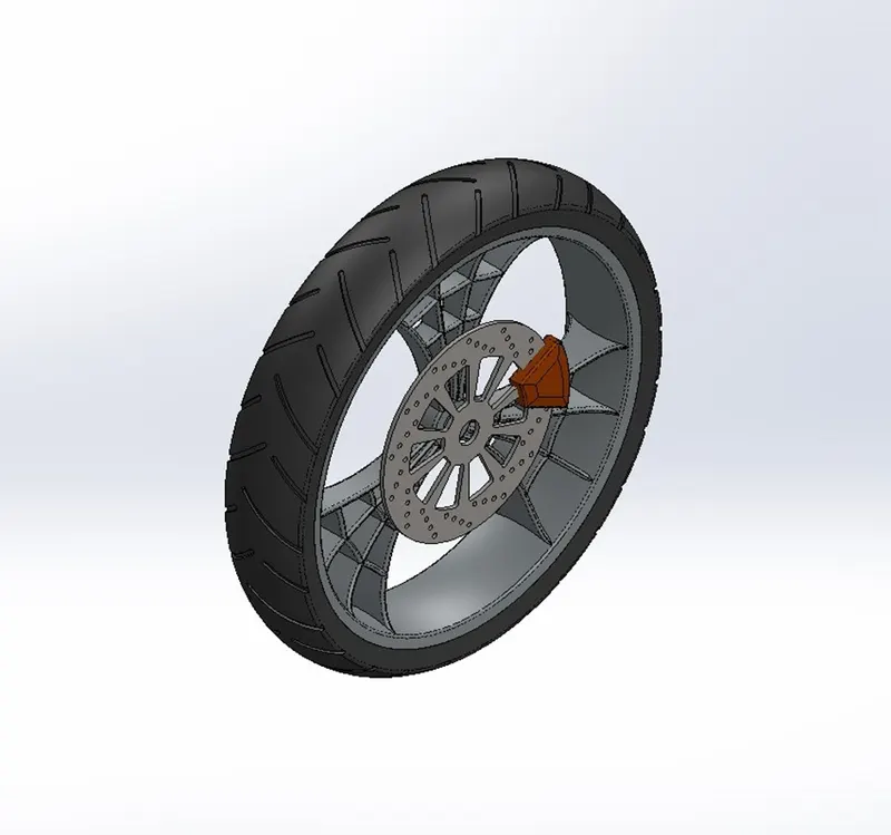
- A wheel is the most crucial element of the chopper. It allows the rider to roll over the ground with great speed and efficiency.
- A wheel is a combination of rim and tire.
- The wheel rim is made up of alloy or steel material and the tire is made up of rubber material and it has a thin metal wire inside it.
FEATURES USED FOR MODELLING THE FRONT WHEEL:
- Sketch
- Offset entities
- Extend entities
- Trim entities
- Sketch fillet
- Revolve boss
- Extrude boss
- Linear pattern
- Chamfer
- Cut extrude
- Circular pattern
PROCEDURE FOLLOWED FOR MODELLING THE FRONT WHEEL:
- Open a new solid works part.
- We are going to create the geometry on default planes without renaming it.
- Now we created the 2D sketch of front wheel by using the sketch tools and some other commands like offset, trim, extend entities and sketch fillet command.
- Then we applied the relations and dimensions to the sketch to make the sketch fully defined.
- Now we converted the 2D sketch of tire profile into revolved object by using the revolve boss feature.
- Then we created the spider web design of the wheel rim and extruded it using extrude feature.
- Then the extruded rim is patterned into number of instances as per our requirement by using circular pattern.
- Then we sketched the rotor which is attached to the rim of the wheel and then extruded it using extrude boss feature.
- Then the unwanted materials are removed from the rotor by using the extruded cut feature. Then we patterned it to make into number of instances by in a linear path by using linear pattern.
- Then we designed the caliper of the wheel in 2D. Then extruded it by using Extruded boss feature and then applied chamfer to the edges of the caliper and specified appearance is applied to the caliper.
- Now we modelled the front wheel and applied the appearance individually to the rim, tire, rotor and caliper of the front wheel.
- Finally, we saved the model as a “Front Wheel”.
REAR WHEEL:
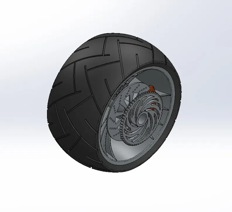
- Rear wheel is mounted to the frame of the chopper with the wheel hub.
- It is a circular object that revolves on axis which is fixed to the wheel hub of frame that enables to roll over on the ground.
- Disk and sprocket are attached with the rear wheel. The chain is connected to the engine and sprocket of the rear wheel for power transmission.
FEATURES USED TO MODEL THE REAL WHEEL:
- Sketch
- Offset entities
- Extend entities
- Trim entities
- Sketch fillet
- Spline
- Revolve boss
- Plane
- Extrude boss
- Revolved cut
- Linear pattern
- Circular pattern
- Extruded cut
- Fillet
- Chamfer
- Appearance
PROCEDURE FOLLWED FOR MODELLING THE REAR WHEEL:
- Open a new solid works part.
- Here we are going to model the rear wheel in default planes that comes in solid works.
- Now select front plane and start sketching.
- Now the 2D sketch of tire profile of rear wheel is sketch in default planes by using the sketch tools.
- Here we also used the sketch fillet command, spline command, offset entities, extend entities and trim entities commands.
- Then we applied the relations and dimensions of the sketch as per the given data.
- Then the 2D sketch of tire profile is converted into revolved object by using revolved boss.
- Then we sketched the wheel rim in 2D and applied the dimensions and relations to the sketch to make it fully defined.
- Then we extruded the sketch by using extruded boss feature and then we removed the unwanted material from the wheel rim to look like a spider web pattern or design.
- Then we patterned the spider web designed rim using the circular pattern feature.
- Then we sketched the rotor or disk of the wheel in 2D by using the sketch tools and applied the relations and dimensions of the sketch to make it fully defined.
- Then we extruded the rotor sketch using extruded boss feature and the unwanted material from the rotor is removed by using the extruded cut feature.
- Then we patterned the extruded cut design in linear path using linear pattern feature and the linear patterned design is patterned through out the rotor in a circular form by using the circular pattern feature.
- Then we designed the sprocket of the wheel in 2D using the sketch tools and extruded the sketch by using the extrude boss feature.
- Then we removed some material from the sprocket and the removed material design is patterned in a circular form by using circular pattern.
- Then we removed the material from that sprocket at the edges to make it like a gear shape to fix the chain on it.
- Finally, we applied appearances individually to the model and saved as a “Rear Wheel”.
FRONT FORK:
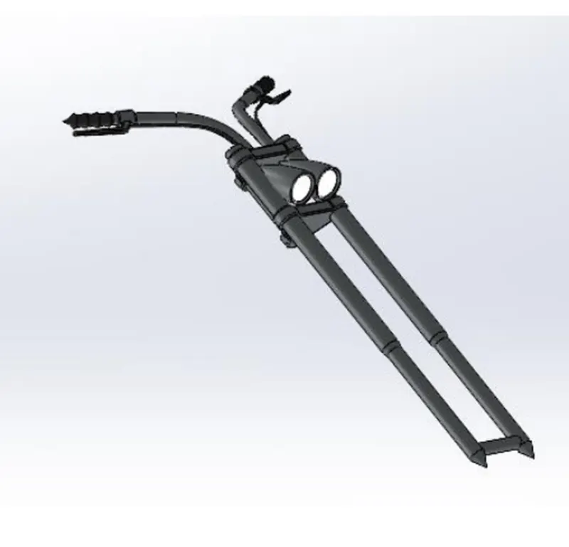
- In today’s world, most of the motorcycle manufactures using a telescopic fork for the front suspension.
- Simply the forks are large hydraulic shock absorbers with internal coil springs.
- It allows the forks to absorb the shocks that occurred while due to the imperfections in the road and gives a comfortable ride to the rider.
- It helps us to rotate the front wheel according to the left and right direction.
FEATURES USED IN MODELLING THE FRONT FORK:
- Sketch
- Extrude boss
- Trim entities
- Revolve boss
- Split tool
- Mirror
- Reference planes.
- Dome
- Combine
- Projected curve
- Sweep
PROCEDURE FOLLWED FOR MODELLING THE FRONT FORK:
- Now open a new solid works part.
- We are going to create geometry on the default planes that comes in solid works.
- Now select the front plane and start sketching on it.
- We sketched the forks in 2D and then the relations and dimensions are given as per the requirement to make the sketch fully defined.
- After that, the 2D sketch is converted in revolved object by using the revolved boss feature.
- Then we sketched the bucket of the light in reference plane and the relations and dimensions are given.
- Then the sketch is converted into revolved object by using the revolve boss feature.
- We now sketched the triple clamps and given the relations and dimensions of the sketch and extruded it by using extrude boss feature.
- Then fillets and chamfers are applied at the required areas of the model.
- Then we sketched the handle bars and here we used projective curve option to make the sketch as per our requirement and swept is created using swept boss feature.
- Finally, appearance of the model is applied and saved as a “Front fork”.
CHASIS:
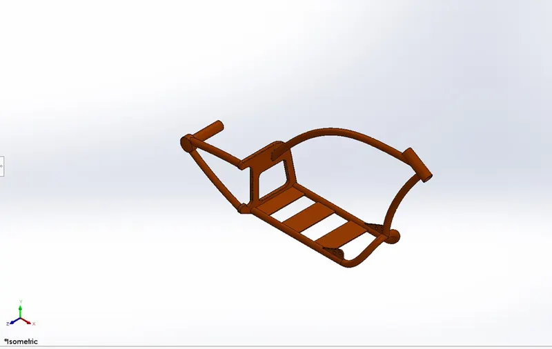
- A chasis is the skeleton of the chopper. It holds the other components of the chopper such as engine, oil tank, front wheel, front fork, gas tank, pedal, kick stand.
- It provides the strength and ability to handle the chopper.
FEATURES USED TO MODEL THE CHASIS:
- Sketch
- Offset
- Extrude boss
- Trim entities
- Offset entities
- Projective curve
- Sweep
- Split tool
- Revolve boss
- Cut extrude
- Fillet
- Combine
- Appearance
PROCEDURE FOLLWED TO MODEL THE CHASIS:
- Open the new solid works part.
- Before creating the geometry, we need to rename the default planes as follows.
- Top plane – Bottom plane Chasis.
- Midplane – Midplane Chasis.
- Front plane – Bottom plane Chasis.
- Insert the sketch picture, then make the alignment as per the requirement by giving the axes values.
- Then select midplane chasis and start sketching on it.
- We sketched the chasis in 2D and the relations and dimensions of the sketch is given as per the requirement to make the sketch fully defined.
- We also used some other commands like spline, offset entities, trim entities and projective curve to make the sketch fully defined.
- Then we converted the sketch in 3D model by using the features like revolve boss, extrude boss and cut extrude features.
- Then the fillets are applied to the model as per the requirement.
- Finally, required appearances are applied to the model to make it complete object and saved the part as “Chasis”.
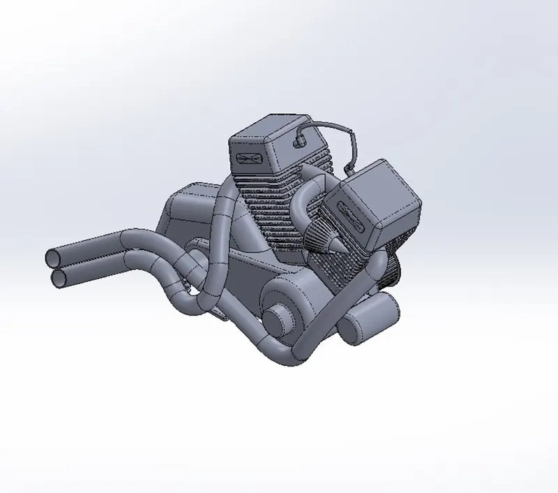
ENGINE:
- An engine is the prime mover of the bike. It provides the necessary power to drive the vehicle.
- Engine consists of piston, connecting rod, inlet valve, outlet valve, crankshaft, crank pin and cylinder.
- An engine converts the chemical energy (Fuel) into heat energy and that heat energy is converted into mechanical energy to do a mechanical work.
- The mechanical work in the engine is a rotary motion.
- The rotary motion is transmitted to the rear wheel with the help of chain and sprocket through the clutch and gear box.
FEATURES USED TO MODEL THE ENGINE:
- Sketch
- Trim
- Revolve boss
- Extrude boss
- Extruded cut
- Offset entities
- Dome
- Fillet
- Projective curve
- Composite curve
- Sweep boss
- Mirror
- Circular pattern
- Split
PROCEDURE FOLLOWED FOR MODELLING THE ENGINE PART:
- Open a new solid works part document.
- We are going to sketch in the default planes that comes in solid works.
- Select front plane and start sketching on it.
- Insert the sketch picture for a reference and make an alignment by adjusting the axes value of the sketch picture.
- The bottom section of the engine is 2D and the relations and dimensions are applied to the sketch.
- Then it is extruded by using the extrude boss feature.
- Then the engine cylinder and cooling fins are sketched in 2D and then it is extruded by using extrude boss feature.
- Then fillets are applied to the cooling fins of the engine and then some unwanted materials are removed by using the extrude cut feature.
- The cooling fins are patterned by in linear path by using the linear pattern feature.
- Then the engine cylinder is mirrored and the spark plug is designed and revolved using revolve boss feature and fillets are applied to it.
- Then the exhaust is designed and her we also used projective curve command and composite curve feature to make the exhaust as per our requirement.
- Then the exhaust is converted into 3 model by using swept boss feature. And then some material is removed from the exhaust end by using split tool.
- Finally fillets at required area is applied and appearance is given to the engine component.
- At last, this model is saved as an “Engine”.
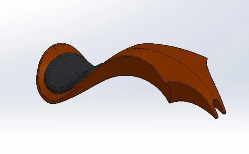
GAS TANK:
- Gas tank covers the oil tank, engine and also acts as a shield that prevents the heat from the engine.
- The seat and opening part of fuel tank is located at the top of gas tank.
FEATURES USED TO MODEL THE GAS TANK:
- Sketch
- Trim entities
- Offset entities
- Spline command
- Projective curve
- Sweep surface
- Loft surface
- Fill surface
- Trim surface
- Knit surface
- Swept cut
- Fillet
- Mirror
- Appearance
PROCEDURE FOLLOWED TO MODEL THE GAS TANK:
- Open a new solid works part.
- Before start sketching, we need to rename the default planes as follows:
- Front plane – Midplane fuel tank.
- Top plane – Bottom plane fuel tank
- Right plane – Front plane fuel tank
- Now select the midplane fuel tank and start sketching on it.
- The 2D sketch of the half of the gas tank is sketched using the sketch tools and some other tools like spline, etc.
- Then the relations and dimensions of the sketch is applied as per the given values to make the sketch fully defined.
- Now the 2D sketch is converted into 3D object by using sweep surface feature.
- Then the loft surface is used to create the lofted surface of the gas tank.
- Now we modeled the half component of gas tank. We used mirror command to mirror the half part of gas tank to make a completed object.
- Now we sketch the seat in 2D and extruded it by using the extrude boss feature. Here we also used offset entities while sketching the seat of the chopper. And we also used the knit surface feature to knit the surfaces of gas tank.
- Now the fillets are applied to the gas tank at required are by giving the radius.
- And now some material from the gas tank is removed by using the swept cut feature.
- Finally, we given the appearance to the gas tank and seat of the chopper.
- The model is saved as a “Gas Tank”.
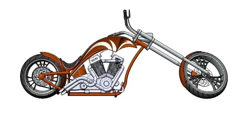
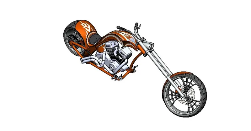
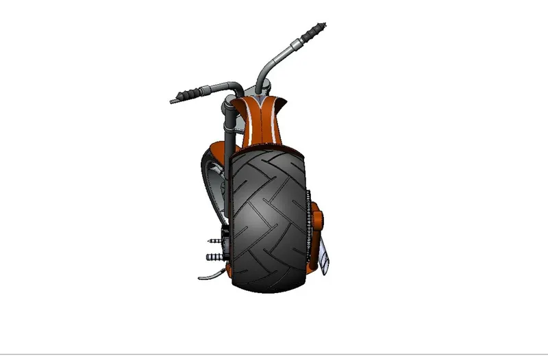
ASSEMBLY OF THE CHOPPER:
- All the individual parts modelled in solid works part document are imported to the assembly by using insert part option in assembly tab by giving some mate conditions.
- Initially, the chasis is inserted into assembly tab by using insert part option and fixed it accordingly.
- Then other individual parts are inserted to the assembly part and fixed to the chasis by giving some mate options like angle mate, coincident mate, parallel mate, etc.
PHOTOVIEW 360:
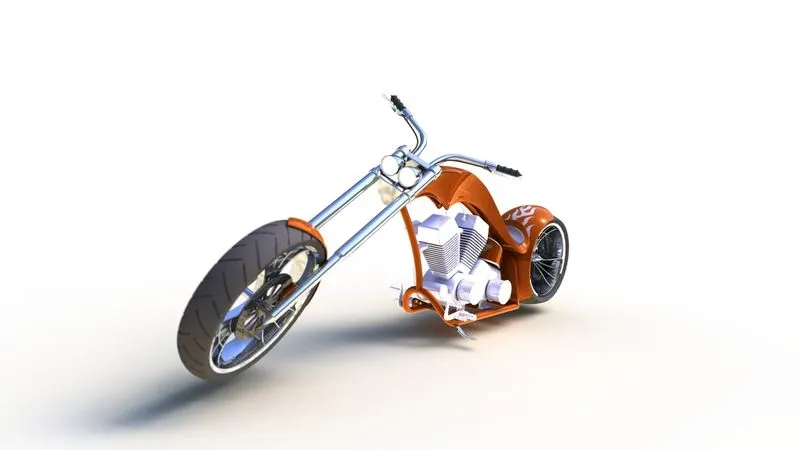
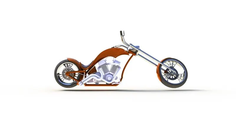
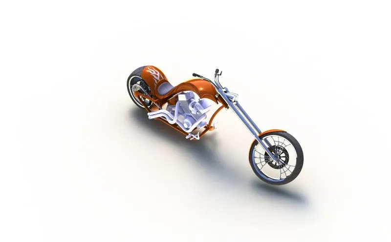
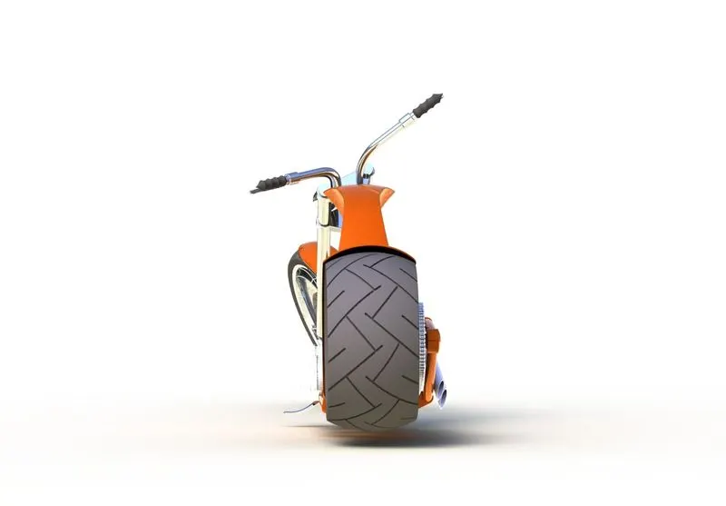
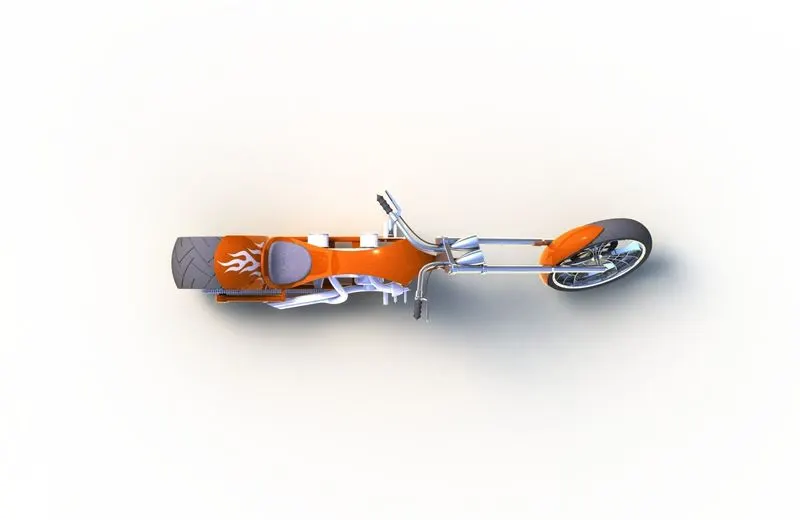
- Photo view 360 is a visualization and rendering solution includes with the solid works.
- It provides highly interactive environment for viewing designs as well as for creating photo-realistic rendering which is used to showcase our designs as well.
RENDERING:
- Rendering is a process of creating realistic images of the photo realistic model with the environment.
- Rendering can be done by two ways in solid works.
- Photo view 360.
- Solid works visualize.
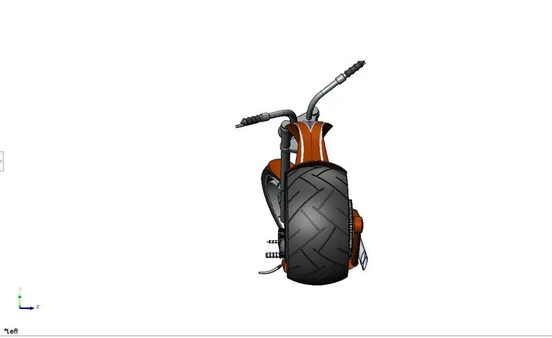
RENDERED IMAGES USING SOLIDWORKS PHOTOVIEW 360:
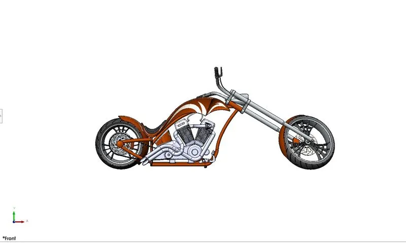
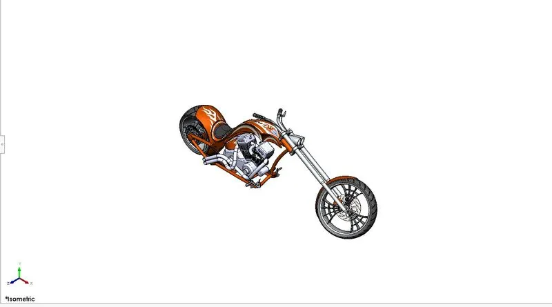
Additional Views:
SOLIDWORKS VISUALIZE:
- Solid works visualize is a photo-realistic rendering tool that utilizes our solid works model to create the high-quality images or commercial quality animations.
- Solid works visualize (formerly known as bunk speed) provides a suite of stand-alone software tools that combine industry leading rendering capabilities with visual design-oriented features and workflows, allowing easy and fast creation of visual content that communicates a designs vision, passion and emotion.