Wiring harness design assembly in CATIA V5 - 3D modeling Weeks 5 & 6 Challenge
WIRING HARNESS ASSEMBLY OF HARNESS 'A' AND HARNESS 'B':
Aim:
To create the wiring harness routing assembly of Harness A and Harness B with the given components as per the given data.
Objective:
- To create the wiring harness routing seperately for 'Harness A' and 'Harness B'
- To create the wiring harness assembly of Harness A and B.
- To add the annotations to the connectors.
Define the mechanical components electrically and prepare the catalogue for the connectors:
Connectors for Harness ‘A’:
Product code – C-DT04-08PA-C017
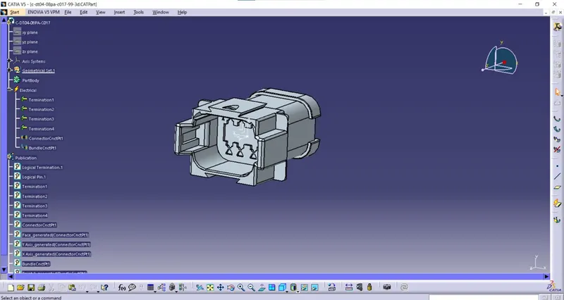
Step 1 – Downloaded the connector from the week 5 and week 6 challenges.
Step 2 – Geometrical parameters
- Switch to part design
- Created point at bundle entry side and connector connection side.
- Created axis system at connector connection side.
- X – axis towards the locking mechanism
- Y – axis towards the front face of the connector
- Z – axis across the connector from top to bottom.
Step 3 – Define part as a connector.
- Switch to electrical part design.
- Select the define connector command.
- Select the geometry.
- Type = single
- No of terminations = 4
Step 4 – Define bundle connection point.
- Switch to electrical part design.
- Select bundle connection point command.
- Select the geometry.
- Name = we can rename it or keep default.
- Representation – select the bundle entry face of connector.
- Point – select the point that we created at bundle entry side.
- Initial condition – select the bundle entry face of connector.
Step 5 – Define connector connection point.
- Switch to electrical part design.
- Select the connector connection point command.
- Select the geometry.
- Name – keep default or rename it.
- Representation – Select the point that we created at connector connection side.
- Contact – select the front face of mating face of connector.
- Coincidence – select y – axis.
- Orientation – select x – axis.
Catalogue:
- Select file > new > catalogue document > add family > Name – connector > Type – Electrical.
Adding created part file into catalogue:
- Open the Connector part file
- Switch to electrical part design.
- Select store device
- Catalogue – select the connector catalogue which is saved already in the device.
- Family – Connectors.
Product code – C-1174357-2:
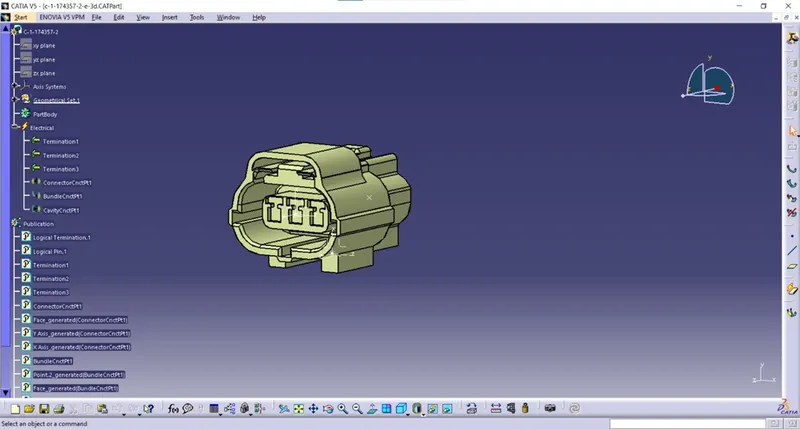
Step 1 – Downloaded connector from the week 5 and week 6 challenges.
Step 2 – Geometrical parameters.
- Switch to part design
- Created point at bundle entry side and connector connection side and also created point for cavity connection at the bottom edge of the connector.
- Created axis system at connector connection side.
- X – axis towards the locking mechanism
- Y – axis towards the front face of the connector
- Z – axis across the connector from left to right.
Step 3 – Define part as a connector.
- Switch to electrical part design.
- Select the define connector command.
- Select the geometry.
- Type = single
- No of terminations = 3
Step 4 – Define bundle connection point.
- Switch to electrical part design.
- Select bundle connection point command.
- Select the geometry.
- Name = we can rename it or keep default.
- Representation – select the bundle entry face of connector.
- Point – select the point that we created at bundle entry side.
- Initial condition – select the bundle entry face of connector.
Step 5 – Define connector connection point.
- Switch to electrical part design.
- Select the connector connection point command.
- Select the geometry.
- Name – keep default or rename it.
- Representation – Select the point that we created at connector connection side.
- Contact – select the front face of mating face of connector.
- Coincidence – select y – axis.
- Orientation – select x – axis.
Step 5 – Define cavity connection point:
- Switch to electrical part design.
- Select the cavity connection point command.
- Select the geometry.
- Name – keep default or rename it.
- Representation – select the point which is created for the cavity connection.
- Contact – select the face which is going to mate with the mounting clip( If any )
- Coincidence – select y – axis.
- Orientation – select x – axis.
Adding created part file into catalogue:
- Open the Connector part file
- Switch to electrical part design.
- Select store device
- Catalogue – select the connector catalogue which is saved already in the device.
- Family – Connectors.
Product code – C-DT06-08SA-CE01
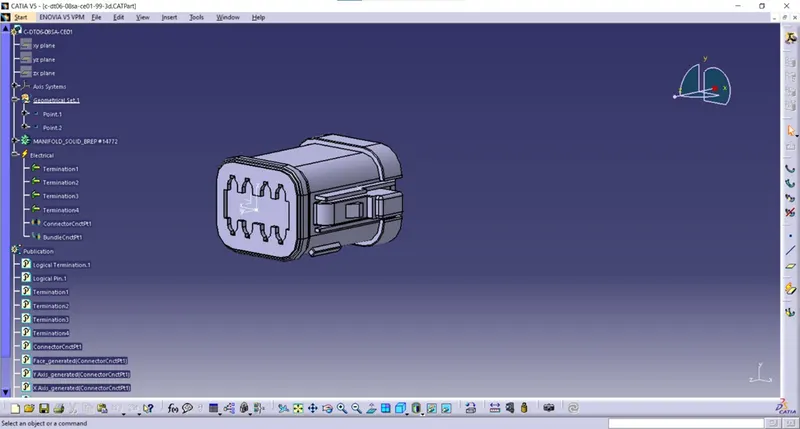
Step 1 – Downloaded the connector from the week 5 and week 6 challenges
Step 2 – Geometrical parameters.
- Switch to part design.
- Created point at bundle entry side and connector connection side.
- Created axis system at the connector connection side.
- X – axis towards the locking mechanism of the connector.
- Y – axis toward the mating side of the connector.
- Z – axis across the top or bottom of the connector.
Step 3 – Define part as a connector.
- Switch to electrical part design.
- Select the define connector command.
- Select the geometry.
- Type = single
- No of terminations = 4
Step 4 – Define bundle connection point.
- Switch to electrical part design.
- Select bundle connection point command.
- Select the geometry.
- Name = we can rename it or keep default.
- Representation – select the bundle entry face of connector.
- Point – select the point that we created at bundle entry side.
- Initial condition – select the bundle entry face of connector.
Step 5 – Define connector connection point.
- Switch to electrical part design.
- Select the connector connection point command.
- Select the geometry.
- Name – keep default or rename it.
- Representation – Select the point that we created at connector connection side.
- Contact – select the front face of mating face of connector.
- Coincidence – select y – axis.
- Orientation – select x – axis.
Add the file into catalogue:
- Switch to electrical part design.
- Select store device.
- Catalogue – select the connector catalogue that we already created and saved in the device.
- Family – Connectors.
Product code – C-DT06-08SA-EP07:
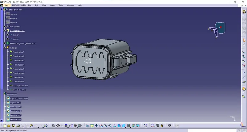
Step 1 – Downloaded the connector from week 5 & 6 challenges.
Step 2 – Geometrical parameters.
- Switch to part design.
- Created point at bundle entry side and connector connection side.
- Created axis system at the connector connection side.
- X – axis towards the locking mechanism of the connector.
- Y – axis toward the mating side of the connector.
- Z – axis towards the top side.
Step 3 – Define part as a connector.
- Switch to electrical part design.
- Select the define connector command.
- Select the geometry.
- Type = single
- No of terminations = 8
Step 4 – Define bundle connection point.
- Switch to electrical part design.
- Select bundle connection point command.
- Select the geometry.
- Name = we can rename it or keep default.
- Representation – select the bundle entry face of connector.
- Point – select the point that we created at bundle entry side.
- Initial condition – select the bundle entry face of connector.
Step 5 – Define connector connection point.
- Switch to electrical part design.
- Select the connector connection point command.
- Select the geometry.
- Name – keep default or rename it.
- Representation – Select the point that we created at connector connection side.
- Contact – select the front face of mating face of connector.
- Coincidence – select y – axis.
- Orientation – select x – axis.
Add the file into catalogue:
- Switch to electrical part design.
- Select store device.
- Catalogue – select the connector catalogue that we already created and saved in the device.
- Family – Connectors.
Product code – C-YDTS26F15-35SNV001:
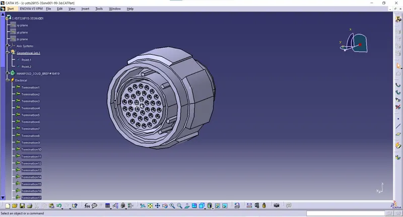
Step 1 – Downloaded the connector from week 5 & 6 challenges.
Step 2 – Geometrical parameters.
- Switch to part design.
- Created point at bundle entry side and connector connection side.
- Created axis system at the connector connection side.
- X – axis towards the locking mechanism of the connector.
- Y – axis toward the mating side of the connector.
- Z – axis towards the top side.
Step 3 – Define part as a connector.
- Switch to electrical part design.
- Select the define connector command.
- Select the geometry.
- Type = single
- No of terminations = 37
Step 4 – Define bundle connection point.
- Switch to electrical part design.
- Select bundle connection point command.
- Select the geometry.
- Name = we can rename it or keep default.
- Representation – select the bundle entry face of connector.
- Point – select the point that we created at bundle entry side.
- Initial condition – select the bundle entry face of connector.
Step 5 – Define connector connection point.
- Switch to electrical part design.
- Select the connector connection point command.
- Select the geometry.
- Name – keep default or rename it.
- Representation – Select the point that we created at connector connection side.
- Contact – select the front face of mating face of connector.
- Coincidence – select y – axis.
- Orientation – select x – axis.
Add the file into catalogue:
- Switch to electrical part design.
- Select store device.
- Catalogue – select the connector catalogue that we already created and saved in the device.
- Family – Connectors.
Connectors for Harness ‘B’:
Product code – C-YDTS26F15-35SNV001:
Step 1 – Downloaded the connector from week 5 & 6 challenges.
Step 2 – Geometrical parameters.
- Switch to part design.
- Created point at bundle entry side and connector connection side.
- Created axis system at the connector connection side.
- X – axis towards the locking mechanism of the connector.
- Y – axis toward the mating side of the connector.
- Z – axis towards the top side.
Step 3 – Define part as a connector.
- Switch to electrical part design.
- Select the define connector command.
- Select the geometry.
- Type = single
- No of terminations = 37
Step 4 – Define bundle connection point.
- Switch to electrical part design.
- Select bundle connection point command.
- Select the geometry.
- Name = we can rename it or keep default.
- Representation – select the bundle entry face of connector.
- Point – select the point that we created at bundle entry side.
- Initial condition – select the bundle entry face of connector.
Step 5 – Define connector connection point.
- Switch to electrical part design.
- Select the connector connection point command.
- Select the geometry.
- Name – keep default or rename it.
- Representation – Select the point that we created at connector connection side.
- Contact – select the front face of mating face of connector.
- Coincidence – select y – axis.
- Orientation – select x – axis.
Add the file into catalogue:
- Switch to electrical part design.
- Select store device.
- Catalogue – select the connector catalogue that we already created and saved in the device.
- Family – Connectors.
Product code – C-DT06-3S-CP01:
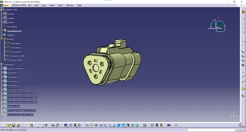
Step 1 – Downloaded the connector from week 5 & 6 challenges.
Step 2 – Geometrical parameters.
- Switch to part design.
- Created point at bundle entry side and connector connection side.
- Created axis system at the connector connection side.
- X – axis towards the locking mechanism of the connector.
- Y – axis toward the mating side of the connector.
- Z – axis towards the top side.
Step 3 – Define part as a connector.
- Switch to electrical part design.
- Select the define connector command.
- Select the geometry.
- Type = single
- No of terminations = 3
Step 4 – Define bundle connection point.
- Switch to electrical part design.
- Select bundle connection point command.
- Select the geometry.
- Name = we can rename it or keep default.
- Representation – select the bundle entry face of connector.
- Point – select the point that we created at bundle entry side.
- Initial condition – select the bundle entry face of connector.
Step 5 – Define connector connection point.
- Switch to electrical part design.
- Select the connector connection point command.
- Select the geometry.
- Name – keep default or rename it.
- Representation – Select the point that we created at connector connection side.
- Contact – select the front face of mating face of connector.
- Coincidence – select y – axis.
- Orientation – select x – axis.
Add the file into catalogue:
- Switch to electrical part design.
- Select store device.
- Catalogue – select the connector catalogue that we already created and saved in the device.
- Family – Connectors.
Product code – C-DT06-08SA-CE04:
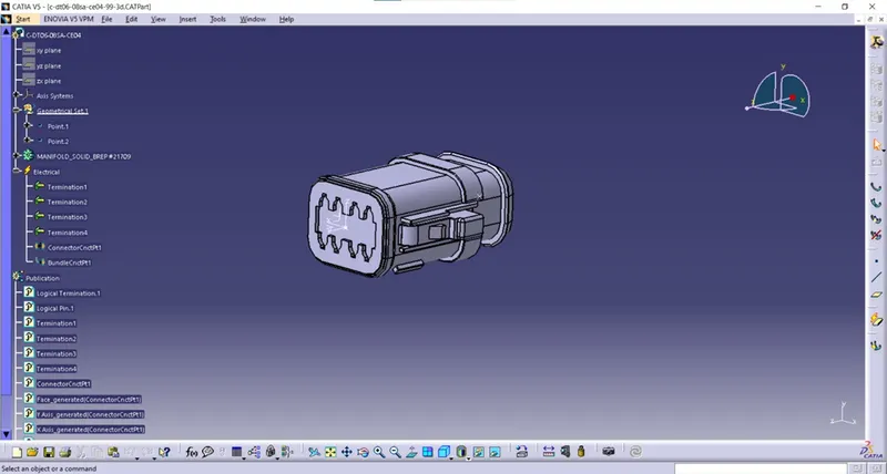
Step 1 – Downloaded the connector from week 5 & 6 challenges.
Step 2 – Geometrical parameters.
- Switch to part design.
- Created point at bundle entry side and connector connection side.
- Created axis system at the connector connection side.
- X – axis towards the locking mechanism of the connector.
- Y – axis toward the mating side of the connector.
- Z – axis towards the top side.
Step 3 – Define part as a connector.
- Switch to electrical part design.
- Select the define connector command.
- Select the geometry.
- Type = single
- No of terminations = 4
Step 4 – Define bundle connection point.
- Switch to electrical part design.
- Select bundle connection point command.
- Select the geometry.
- Name = we can rename it or keep default.
- Representation – select the bundle entry face of connector.
- Point – select the point that we created at bundle entry side.
- Initial condition – select the bundle entry face of connector.
Step 5 – Define connector connection point.
- Switch to electrical part design.
- Select the connector connection point command.
- Select the geometry.
- Name – keep default or rename it.
- Representation – Select the point that we created at connector connection side.
- Contact – select the front face of mating face of connector.
- Coincidence – select y – axis.
- Orientation – select x – axis.
Add the file into catalogue:
- Switch to electrical part design.
- Select store device.
- Catalogue – select the connector catalogue that we already created and saved in the device.
- Family – Connectors.
Product code – C-DT06-08SA-EP07
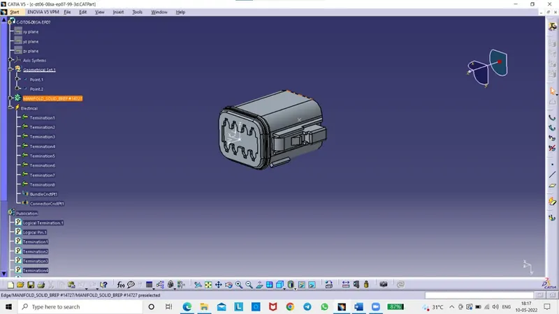
Step 1 – Downloaded the connector from week 5 & 6 challenges.
Step 2 – Geometrical parameters.
- Switch to part design.
- Created point at bundle entry side and connector connection side.
- Created axis system at the connector connection side.
- X – axis towards the locking mechanism of the connector.
- Y – axis toward the mating side of the connector.
- Z – axis towards the top side.
Step 3 – Define part as a connector.
- Switch to electrical part design.
- Select the define connector command.
- Select the geometry.
- Type = single
- No of terminations = 8
Step 4 – Define bundle connection point.
- Switch to electrical part design.
- Select bundle connection point command.
- Select the geometry.
- Name = we can rename it or keep default.
- Representation – select the bundle entry face of connector.
- Point – select the point that we created at bundle entry side.
- Initial condition – select the bundle entry face of connector.
Step 5 – Define connector connection point.
- Switch to electrical part design.
- Select the connector connection point command.
- Select the geometry.
- Name – keep default or rename it.
- Representation – Select the point that we created at connector connection side.
- Contact – select the front face of mating face of connector.
- Coincidence – select y – axis.
- Orientation – select x – axis.
Add the file into catalogue:
- Switch to electrical part design.
- Select store device.
- Catalogue – select the connector catalogue that we already created and saved in the device.
- Family – Connectors.
Product code – C-DT06-08SA-CE13:
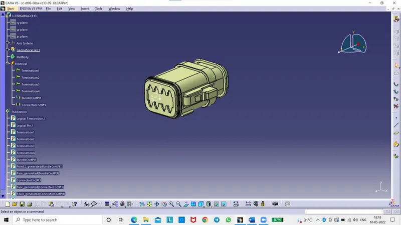
Step 1 – Downloaded the connector from week 5 & 6 challenges.
Step 2 – Geometrical parameters.
- Switch to part design.
- Created point at bundle entry side and connector connection side.
- Created axis system at the connector connection side.
- X – axis towards the locking mechanism of the connector.
- Y – axis toward the mating side of the connector.
- Z – axis towards the top side.
Step 3 – Define part as a connector.
- Switch to electrical part design.
- Select the define connector command.
- Select the geometry.
- Type = single
- No of terminations = 4
Step 4 – Define bundle connection point.
- Switch to electrical part design.
- Select bundle connection point command.
- Select the geometry.
- Name = we can rename it or keep default.
- Representation – select the bundle entry face of connector.
- Point – select the point that we created at bundle entry side.
- Initial condition – select the bundle entry face of connector.
Step 5 – Define connector connection point.
- Switch to electrical part design.
- Select the connector connection point command.
- Select the geometry.
- Name – keep default or rename it.
- Representation – Select the point that we created at connector connection side.
- Contact – select the front face of mating face of connector.
- Coincidence – select y – axis.
- Orientation – select x – axis.
Add the file into catalogue:
- Switch to electrical part design.
- Select store device.
- Catalogue – select the connector catalogue that we already created and saved in the device.
- Family – Connectors.
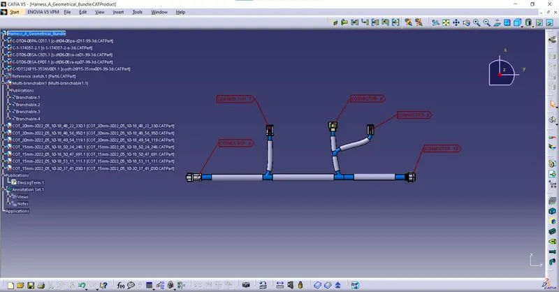
WIRING HARNESS ROUTING FOR HARNESS ‘A’:
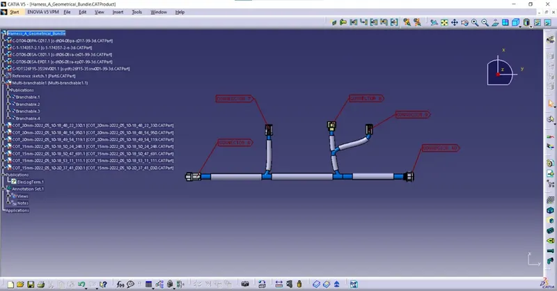
- Opened a new product file and renamed it as a
- Added all the required connectors for creating wiring harness routing for Harness A.
- Switched to mechanical assembly design workbench.
- Arranged the connectors according to the reference image of harness A.
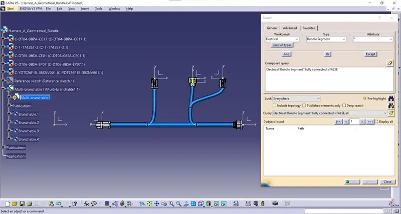
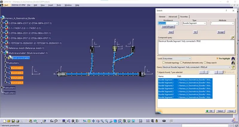
- Now the geometrical bundle file is converted into electrical by using the geometrical bundle command in the electrical harness assembly workbench.
- Now multibranchable file is created by using the command known as Multi-Branchable Document.
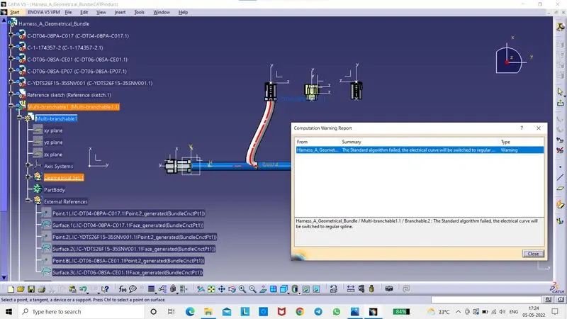
- Now the branches are created between the connectors by using the command called branch definition. After selecting the branch definition, a window pop up, now entered the name of the branch (keep default or rename it), diameter of the bundle and bend radius ratio and slack length if any needed.
- Now selected the route definition and selected the required two connectors and direction of branch should be adjusted by using the reverse tangent option. Now the branch is created between the connectors.
- The same process is used for creating the branches between the other connectors.
- Now the cot tubes with required diameters are applied to the branches which is between the connectors by using the command called protective covering in the electrical harness assembly workbench.
- For applying the cot tubes, selected the protective covering command and selected the branch and selected the required size of cot tube from the saved catalogue. The same process is used for applying the cot tubes to the remaining branches.
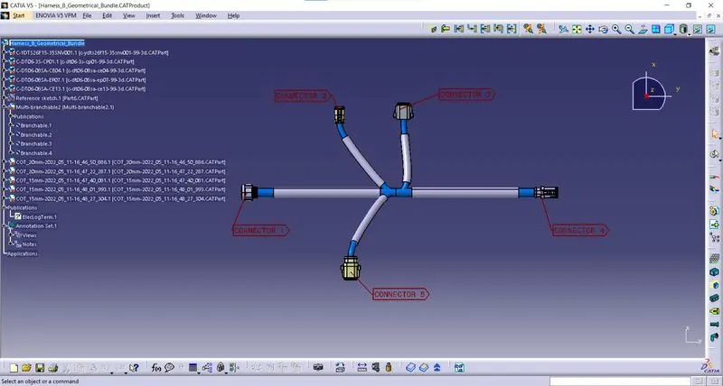
WIRING HARNESS ROUTING FOR HARNESS ‘B’:
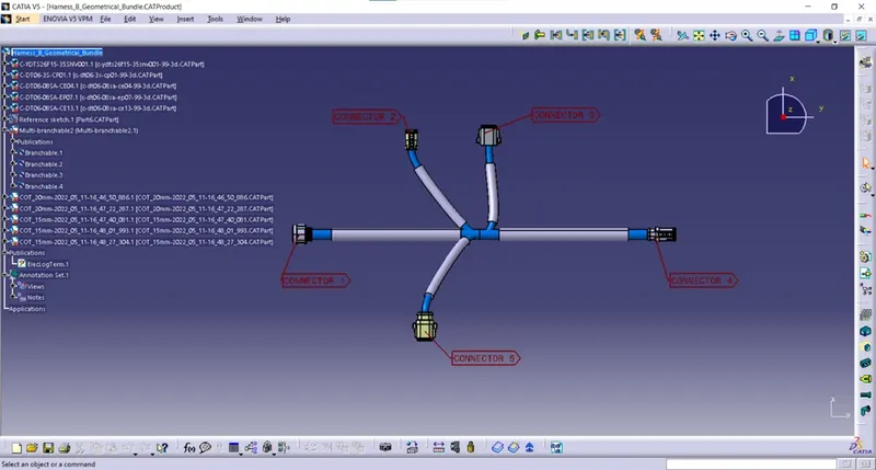
- Opened a new product file and renamed it as a
- Added all the required connectors for creating wiring harness routing for Harness B.
- Switched to mechanical assembly design workbench.
- Arranged the connectors according to the reference image of harness A.
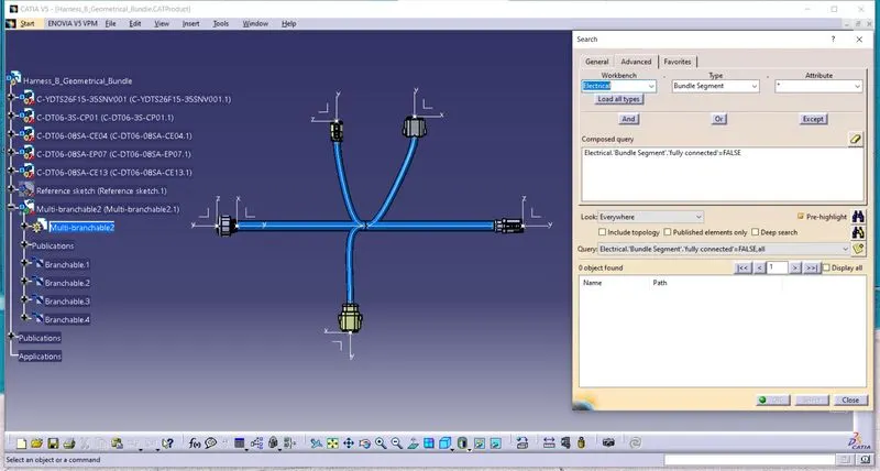
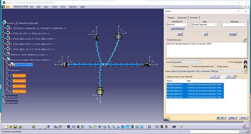
- Now the geometrical bundle file is converted into electrical by using the geometrical bundle command in the electrical harness assembly workbench.
- Now multibranchable file is created by using the command known as Multi-Branchable Document.
- Now the branches are created between the connectors by using the command called branch definition. After selecting the branch definition, a window pop up, now entered the name of the branch (keep default or rename it), diameter of the bundle and bend radius ratio and slack length if any needed.
- Now selected the route definition and selected the required two connectors and direction of branch should be adjusted by using the reverse tangent option. Now the branch is created between the connectors.
- The same process is used for creating the branches between the other connectors.
- Now the cot tubes with required diameters are applied to the branches which is between the connectors by using the command called protective covering in the electrical harness assembly workbench.
- For applying the cot tubes, selected the protective covering command and selected the branch and selected the required size of cot tube from the saved catalogue. The same process is used for applying the cot tubes to the remaining branches.
ADDING ANOTATIONS:
- Switched to mechanical assembly design workbench.
- Select the view creation command for selecting the plane which is for showing the text in required plane direction.
- After that, select the flag note with ladder and add the text and customize the properties of that.
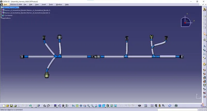
WIRINIG HARNESS ROUTING ASSEMBLY OF HARNESS A AND B:
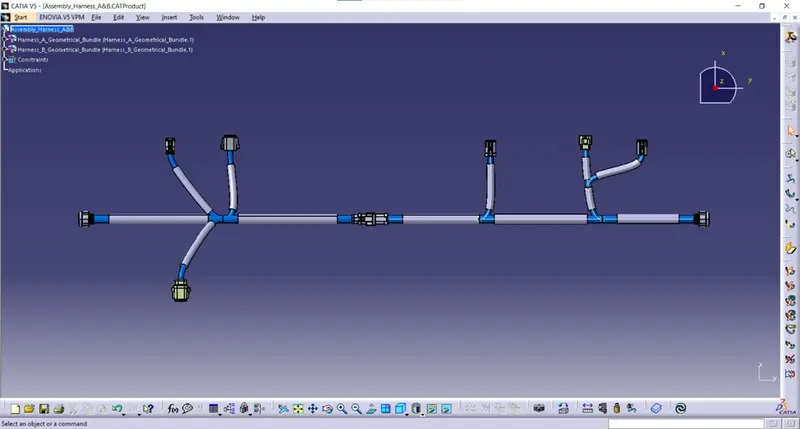
- Opened a new product file and renamed it as a Assemby_Harness_A&B.
- Copied and pasted the Harness_A_Geometrical_Bundle and Harness_B_Geometrical_Bundle into the Assemby_Harness_A&B.
- Switched to the electrical harness assembly workbench.
- The two connectors are connected by using the command called connect electrical devices.
ADDITIONAL IMAGES: