Wiring harness design in CATIA V5 - 3D modeling Week 4 Challenge
Aim:
To create the wiring harness routing as per the given data.
Objective:
- Define the mechanical components (Connectors) elecctrically and prepare catalogue for the connectors.
- To create the wiring harness assembly with electrically defined connectors.
Given data:
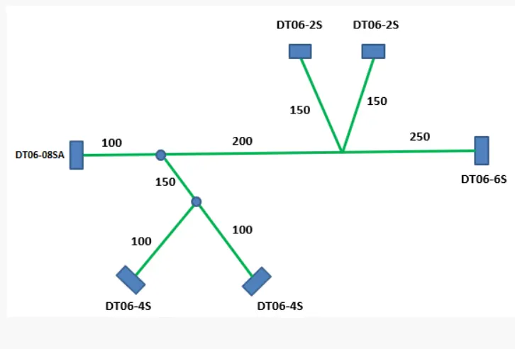
Define the connectors into electrically and prepare catalogue for them:
Steps followed:
Connector:
Product code – DT06-2S
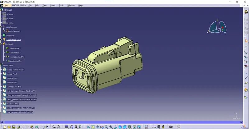
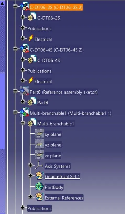
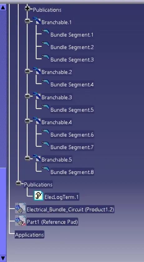
Step 1 – Downloaded the connector cad file from the te.com website.
Step 2 – Geometrical parameters
- Switch to part design
- Created point at bundle entry side and connector connection side.
- Created axis system at connector connection side.
- X – axis towards the locking mechanism
- Y – axis towards the front face of the connector
- Z – axis across the connector from left to right.
Step 3 – Define part as a connector.
- Switch to electrical part design.
- Select the define connector command.
- Select the geometry.
- Type = single
- No of terminations = 2
Step 4 – Define bundle connection point.
- Switch to electrical part design.
- Select bundle connection point command.
- Select the geometry.
- Name = we can rename it or keep default.
- Representation – select the bundle entry face of connector.
- Point – select the point that we created at bundle entry side.
- Initial condition – select the bundle entry face of connector.
Step 5 – Define connector connection point.
- Switch to electrical part design.
- Select the connector connection point command.
- Select the geometry.
- Name – keep default or rename it.
- Representation – Select the point that we created at connector connection side.
- Contact – select the front face of mating face of connector.
- Coincidence – select y – axis.
- Orientation – select x – axis.
Create Catalogue:
- Select file > new > catalogue document > add family > Name – connector > Type – Electrical
Adding created part file into catalogue:
- Open the Connector part file
- Switch to electrical part design.
- Select store device
- Catalogue – select the connector catalogue which is saved already in the device.
- Family – Connectors.
Product code – DT06-4S:
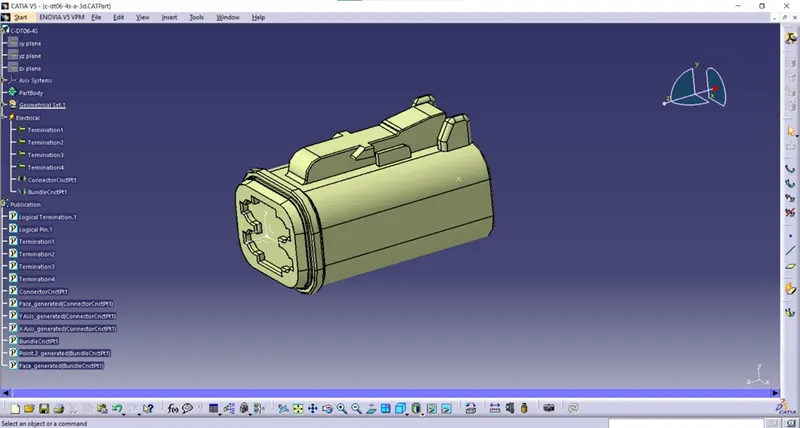
Step 1 – Downloaded connector cad file from te.com website.
Step 2 – Geometrical parameters.
- Switch to part design
- Created point at bundle entry side and connector connection side.
- Created axis system at connector connection side.
- X – axis towards the locking mechanism
- Y – axis towards the front face of the connector
- Z – axis across the connector from left to right.
Step 3 – Define part as a connector.
- Switch to electrical part design.
- Select the define connector command.
- Select the geometry.
- Type = single
- No of terminations = 4
Step 4 – Define bundle connection point.
- Switch to electrical part design.
- Select bundle connection point command.
- Select the geometry.
- Name = we can rename it or keep default.
- Representation – select the bundle entry face of connector.
- Point – select the point that we created at bundle entry side.
- Initial condition – select the bundle entry face of connector.
Step 5 – Define connector connection point.
- Switch to electrical part design.
- Select the connector connection point command.
- Select the geometry.
- Name – keep default or rename it.
- Representation – Select the point that we created at connector connection side.
- Contact – select the front face of mating face of connector.
- Coincidence – select y – axis.
- Orientation – select x – axis.
Add the file into catalogue:
- Switch to electrical part design.
- Select store device.
- Catalogue – select the connector catalogue that we already created and saved in the device.
- Family – Connectors.
Product code – DT06-6S:
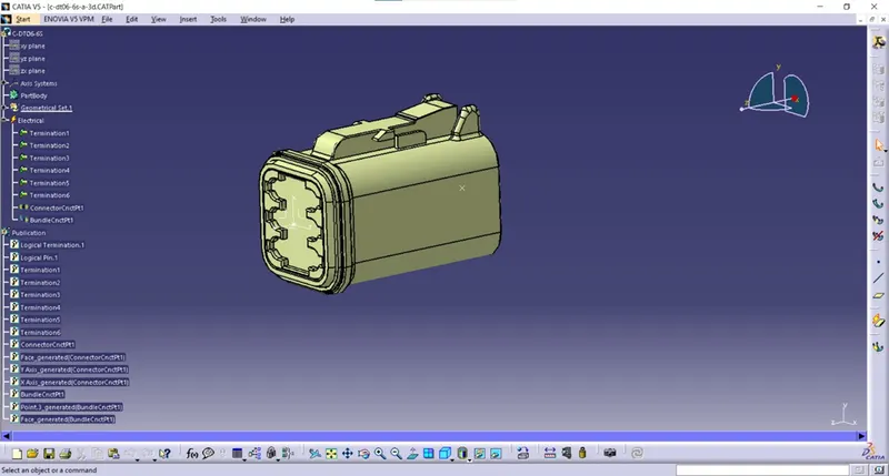
Step 1 – Downloaded the connector cad file from te.com website.
Step 2 – Geometrical parameters.
- Switch to part design.
- Created point at bundle entry side and connector connection side.
- Created axis system at the connector connection side.
- X – axis towards the locking mechanism of the connector.
- Y – axis toward the mating side of the connector.
- Z – axis across the left or right side of the connector.
Step 3 – Define part as a connector.
- Switch to electrical part design.
- Select the define connector command.
- Select the geometry.
- Type = single
- No of terminations = 6
Step 4 – Define bundle connection point.
- Switch to electrical part design.
- Select bundle connection point command.
- Select the geometry.
- Name = we can rename it or keep default.
- Representation – select the bundle entry face of connector.
- Point – select the point that we created at bundle entry side.
- Initial condition – select the bundle entry face of connector.
Step 5 – Define connector connection point.
- Switch to electrical part design.
- Select the connector connection point command.
- Select the geometry.
- Name – keep default or rename it.
- Representation – Select the point that we created at connector connection side.
- Contact – select the front face of mating face of connector.
- Coincidence – select y – axis.
- Orientation – select x – axis.
Add the file into catalogue:
- Switch to electrical part design.
- Select store device.
- Catalogue – select the connector catalogue that we already created and saved in the device.
- Family – Connectors.
Product code – DT06-08SA:
Step 1 – Downloaded the connector cad file from te.com website.
Step 2 – Geometrical parameters.
- Switch to part design.
- Created point at bundle entry side and connector connection side.
- Created axis system at the connector connection side.
- X – axis towards the locking mechanism of the connector.
- Y – axis toward the mating side of the connector.
- Z – axis towards the top side.
Step 3 – Define part as a connector.
- Switch to electrical part design.
- Select the define connector command.
- Select the geometry.
- Type = single
- No of terminations = 8
Step 4 – Define bundle connection point.
- Switch to electrical part design.
- Select bundle connection point command.
- Select the geometry.
- Name = we can rename it or keep default.
- Representation – select the bundle entry face of connector.
- Point – select the point that we created at bundle entry side.
- Initial condition – select the bundle entry face of connector.
Step 5 – Define connector connection point.
- Switch to electrical part design.
- Select the connector connection point command.
- Select the geometry.
- Name – keep default or rename it.
- Representation – Select the point that we created at connector connection side.
- Contact – select the front face of mating face of connector.
- Coincidence – select y – axis.
- Orientation – select x – axis.
Add the file into catalogue:
- Switch to electrical part design.
- Select store device.
- Catalogue – select the connector catalogue that we already created and saved in the device.
- Family – Connectors.
WIRING HARNESS ASSEMBLY ROUTING:
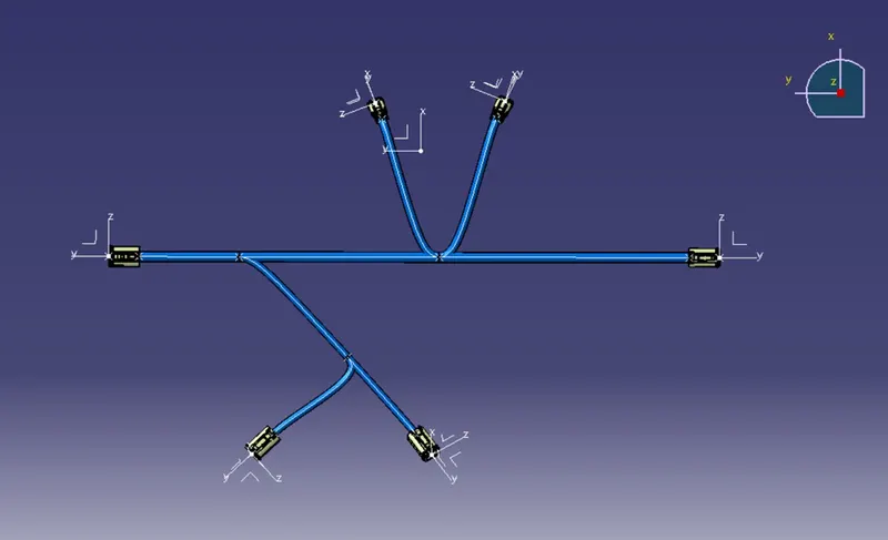
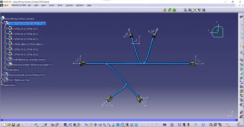
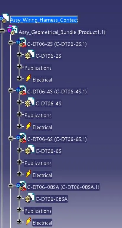
STEPS FOLLOWED FOR WIRING HARNESS ASSEMBLY ROUTING:
- Open a new product file.
- Renamed it to
- Now add one new product file into the
- Now the added product file is renamed to
- Again, added one new product file into the
- That added product file is renamed into Electrical_Bundle_circuit. And hide this Electrical_Bundle_circuit.
- Now open the Assy_Geometrical_Bundle product file into the new window. Browse catalogue and add the DT06-2S, DT06-4S. DT06-6S, DT06-08SA connector part files in it.
- Now one reference pad part file is created for positioning the connectors accordingly and added this part file into
- And also created one reference sketch for aligning the connectors at desired location for creating the bundles between the connectors.
- This reference sketch part file is added into the
- Now copy the DT06-2S connector file and DT06-4S connector file and paste it into the Assy_Geometrical_Bundle
- Saved these files in device and close.
- Now switch to assembly design workbench and positioned the connectors at the desired location by using the reference pad with the help of commands such as manipulate, translate or rotate and snap.
- And now the connector directions are aligned in a way with the base of reference sketch.
- Now switch to electrical harness assembly workbench.
- Select the geometrical bundle command and select the Assy_Geometrical_Bundle in model tree to define electrically.
- Now select multi-branchable document command to create the bundles between the connectors.
- After selecting the multi-branchable document, a window popup and we need to select the bundle diameter and slack percentage (if needed) and select the route definition to select the connectors.
- Now select the DT06-08SA and DT06-6S connectors. Now the bundle is created between the connectors.
- Select the add branch point command to create the branch point between the created bundle and select the bundle and enter the length 100mm to create the branch point at 100mm from the DT006-08SA connector.
- Now again select the add branch point command and select the bundle which is connected with the DT06-6S connector and enter the length of 250mm to create the branch point at 250mm from the DT06-6S connector.
- Now select the branch definition command and select the bundle which we already created and now the window popup and enter the bundle diameter and slack percentage if needed and select the route definition to select the connectors.
- Now select the bundle and select the DT06-2S connector, now the branch is created between the bundle and DT06-2S connector.
- And did the same process for creating the branch for one more DT06-2S connector.
- Now select the branch definition command and enter the diameter and slack percentage if needed and select the route definition and select the bundle which is connected with the DT06-08SA connector and select the DT06-4S connector, now the branch is created between them.
- Then select the add branch point command and select the branch which is connected between the DT06-08SA and DT06-6S and enter the length of 150mm to create the branch at that distance.
- Now select the branch definition command and select the bundle which is connected DT06-4S connector and select the another DT06-4S connector to form the branch between them.
- Finally, the wiring harness assembly routing is created.