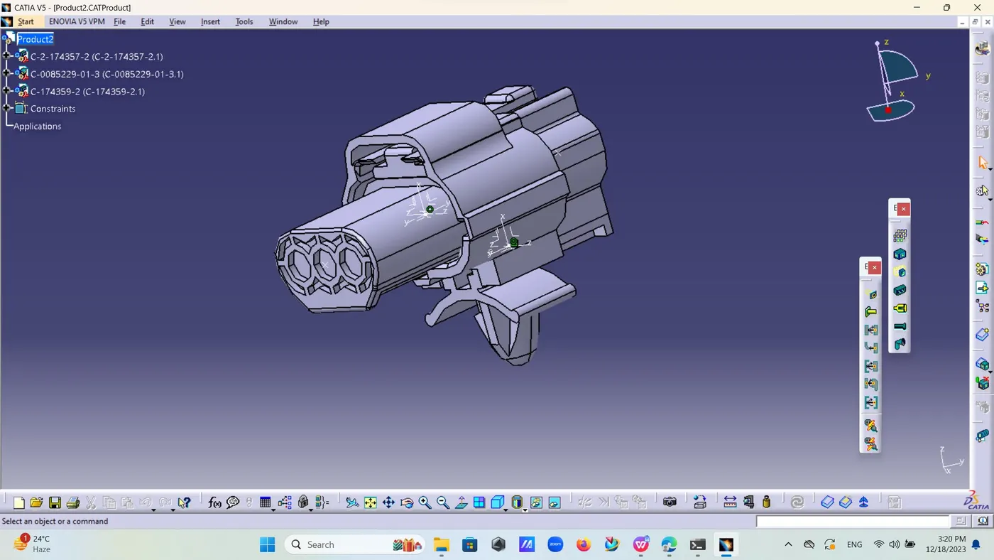
Wiring harness design in CATIA V5 - 3D modeling Week 2 Challenge
Download CAD file of C2-174357-2 socket part of connector and also connector and clip .
First task is to define its geometrical properties as for socket there is three points for wire entry or bundle entry connection define its bundle entry point by selecting point form point plane from reference box and select circle form options the decide boundary entry point .
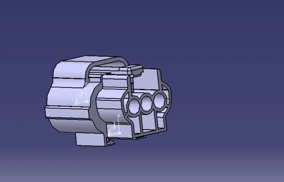
Now,come to the front face and take two corner points and select mid point form them
Now,define axis system there by selecting that mid point as Y axis show towards form and z axis towards side and x axis towards locking direction .
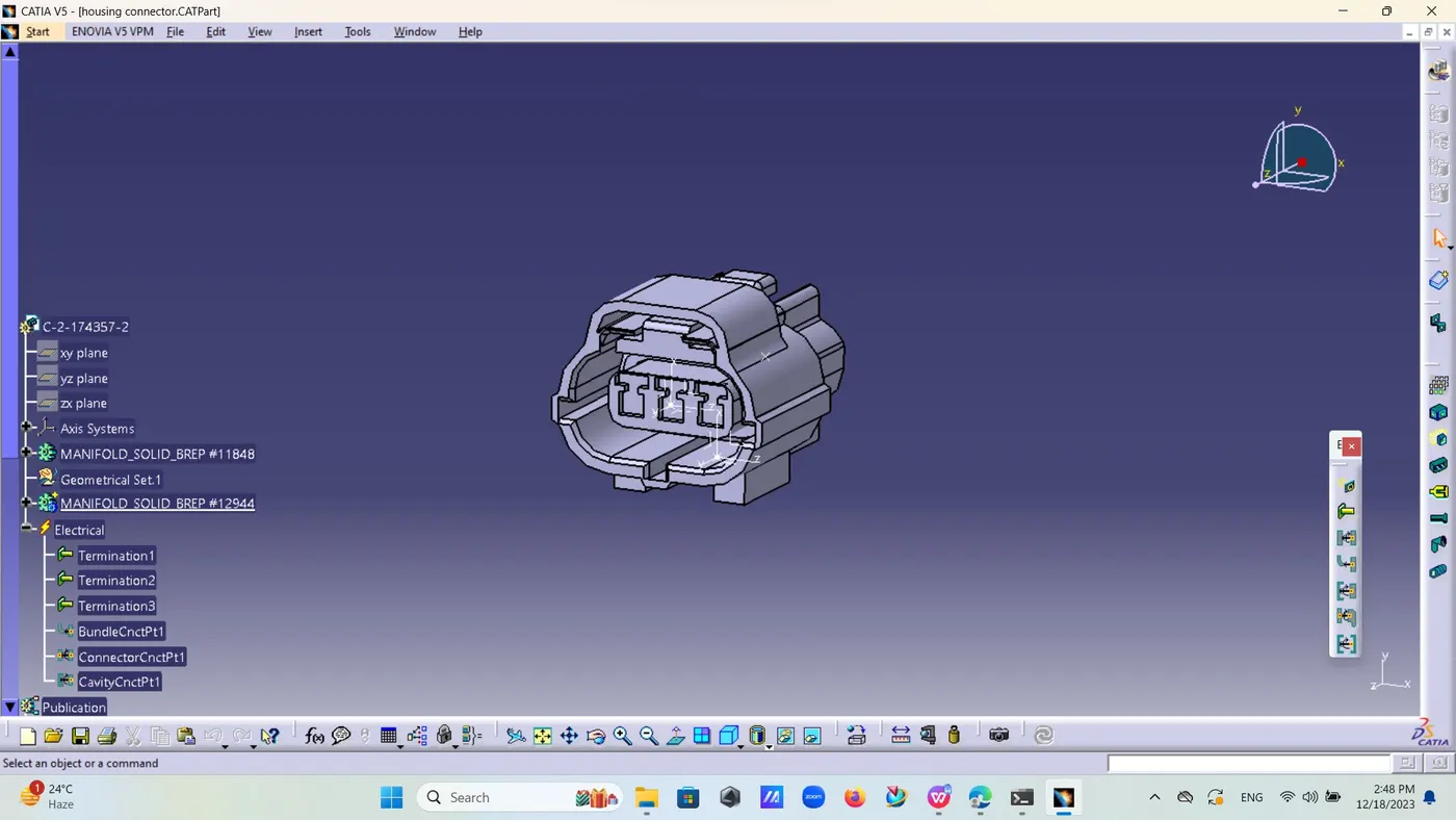
Now,we have to define its electrical properties by selecting electrical part body from start -equipment and system electrical harness discipline electrical part design .
Now chose this component as define connector and then part .
Define connector connection point select mid point as its connector connection point and contact face orientation axis x axis and coincidence axis y axis .
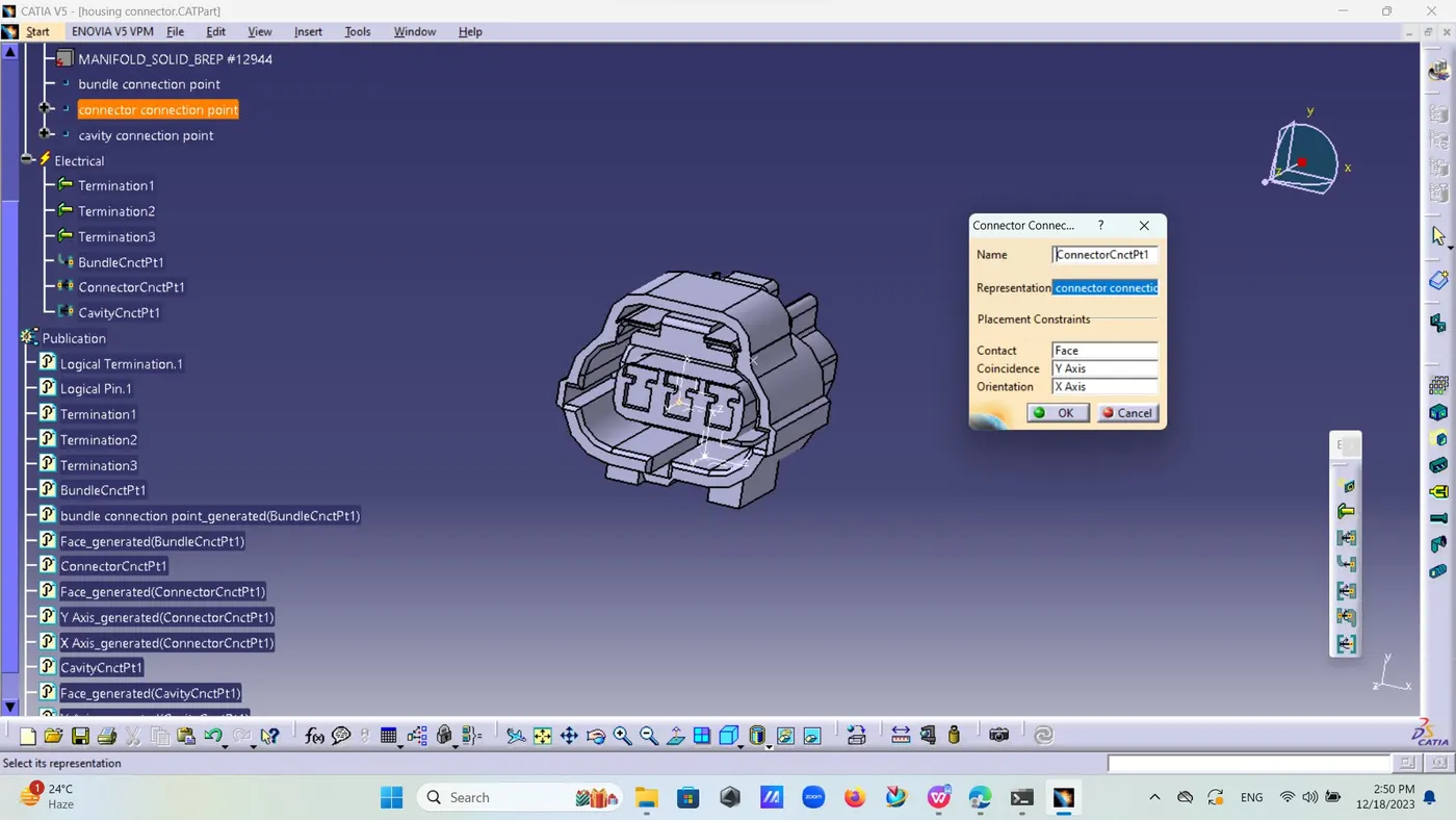
Define bundle connection point and select mid point as bundle connection point representation face initial condition face.
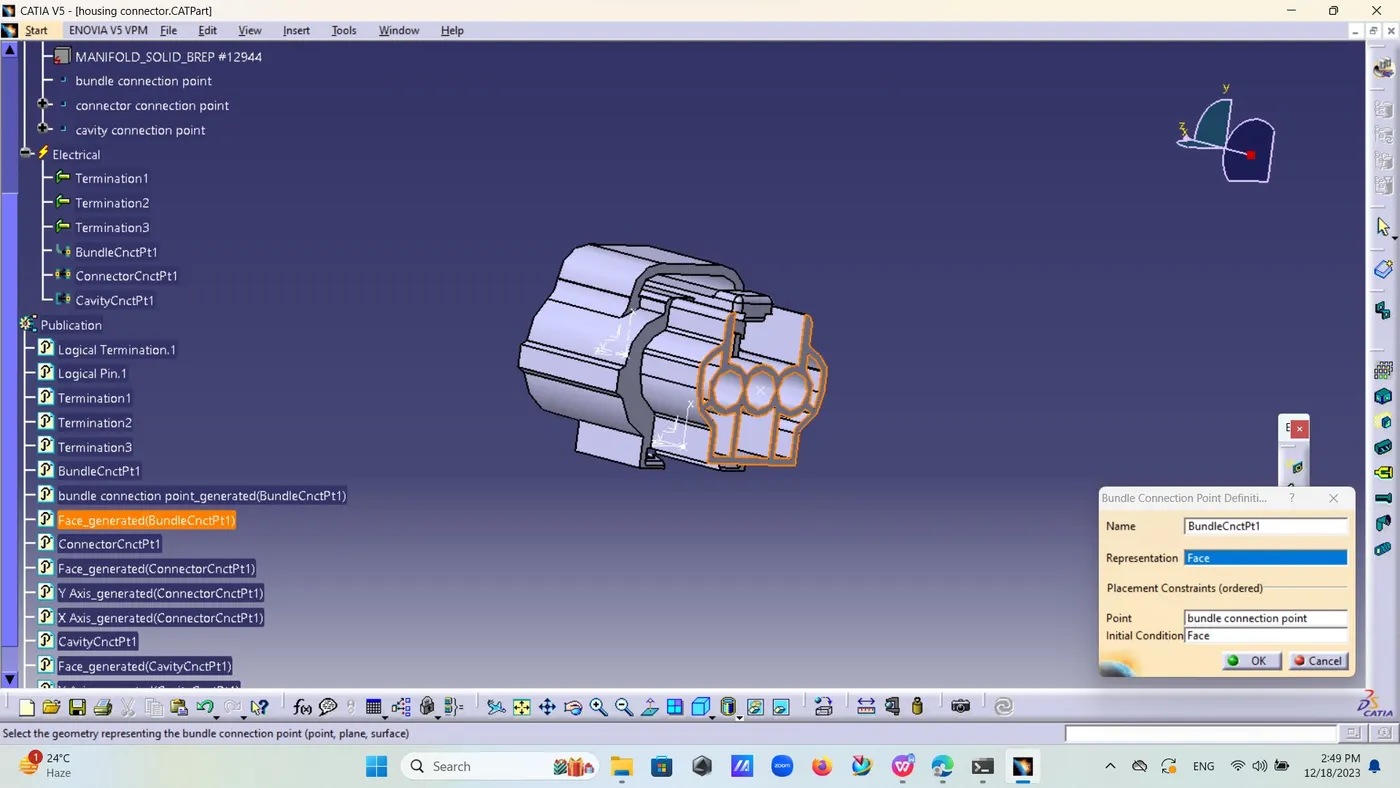
Now there is face provided for clip select that and define mid point for that face then define axis system as for connector connection point y axis facing towards form x axis towards locking direction and z axis horizontal .
Now,define this point as cavity connection point .
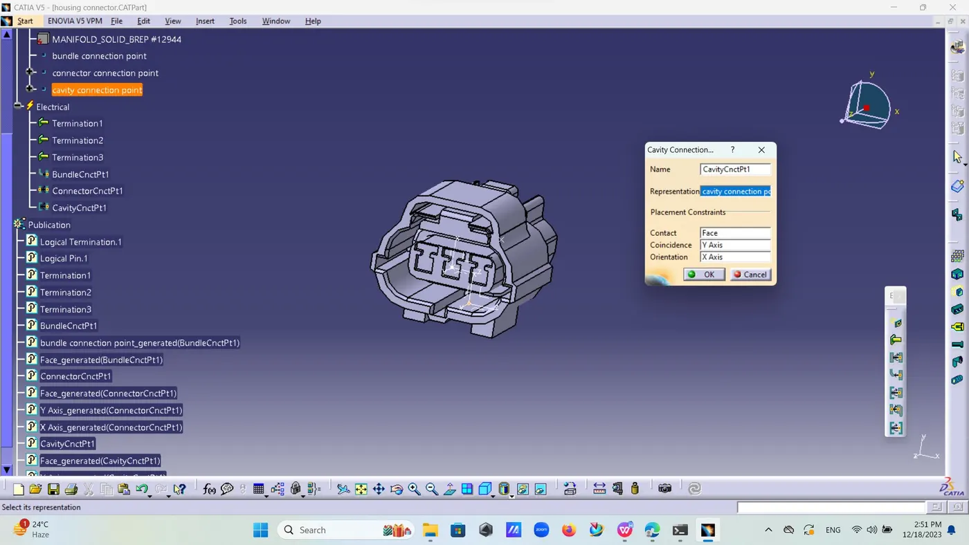
Now ,create one catalogue document and add this as catalogue.
Now,Clip in new part file and define its geometrical properties by taking its mid point and then by defining axis system.in this Y axis facing towards direction as for connector had done and x axis for locking direction .
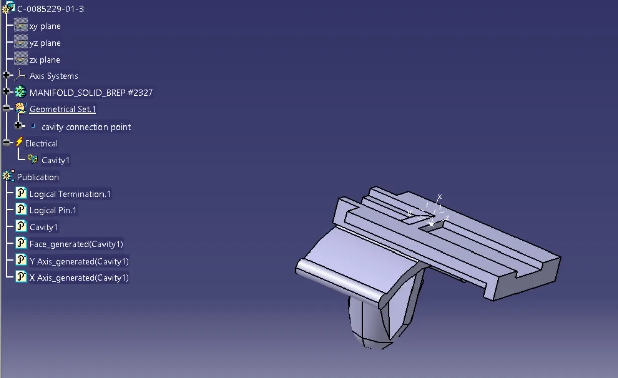
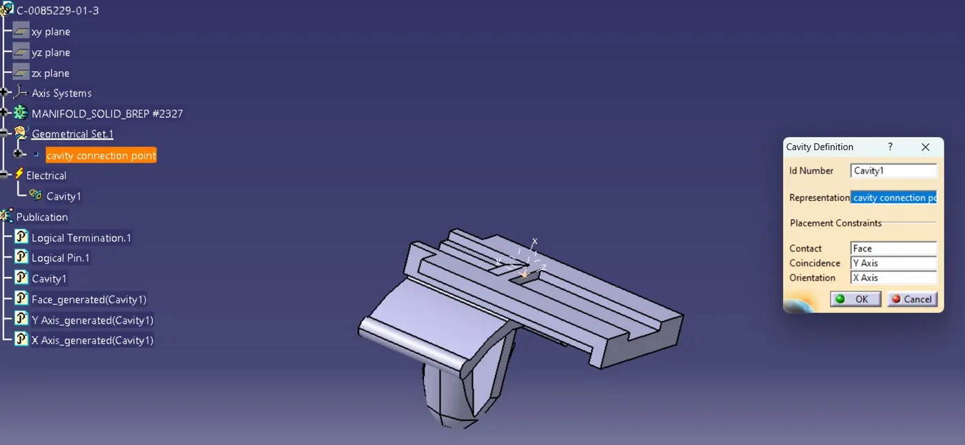
Then define this clip electrically by defining it as cavity connection point.
dwonload second connector C-DT06-08SA
define its geomatrical prperties by selecting budle connection point and connector connection point
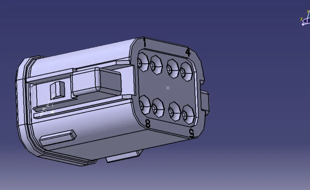
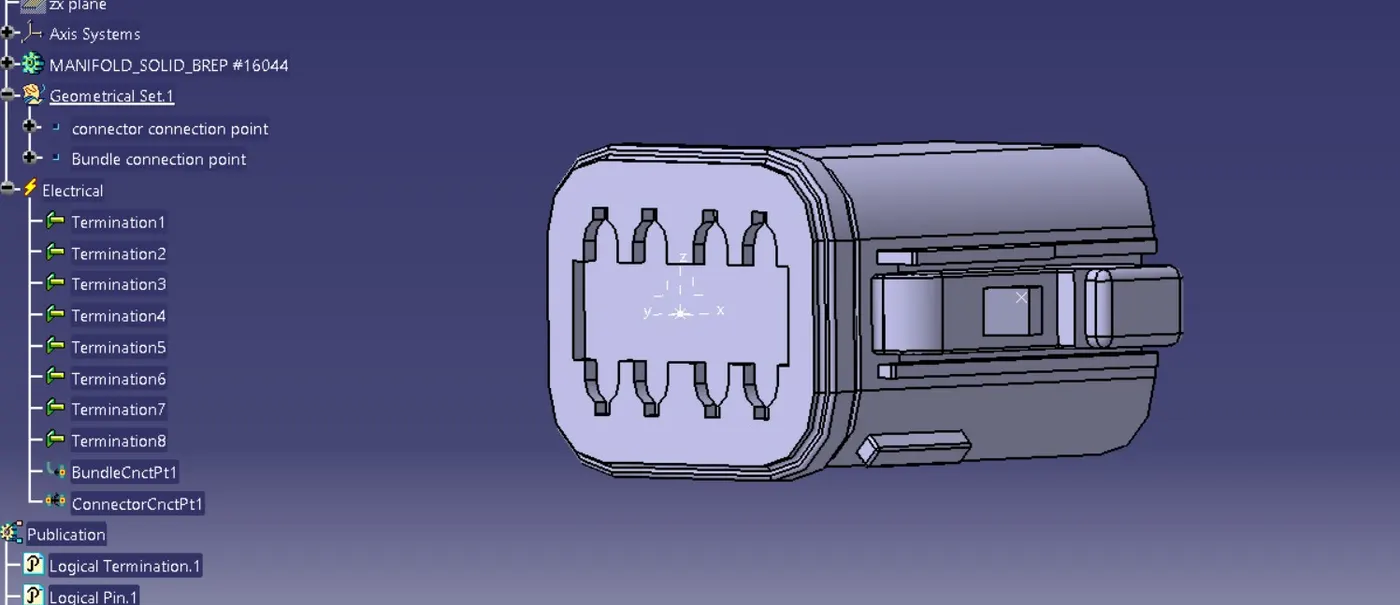
then select ups or co-ordinate system and selct origin as connector connection point
rotatate its Y axis towards front and X axis in locking direction and Z axis in remaining one direction
go to elctrical part desing and select connector and define its electrical properties of connector connection point and bundle connection points .
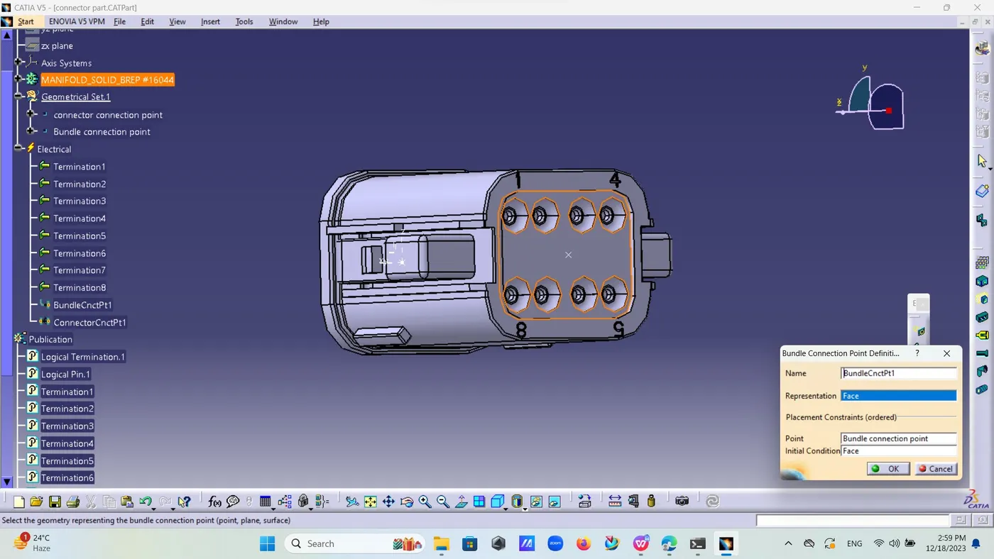
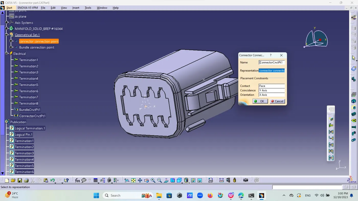
Now ,there third its mating part c-174359-2 download its CAD file and open in catia new part .
Define its geometrical properties by define mid points for bundle entry and connector connection point.
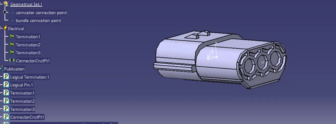
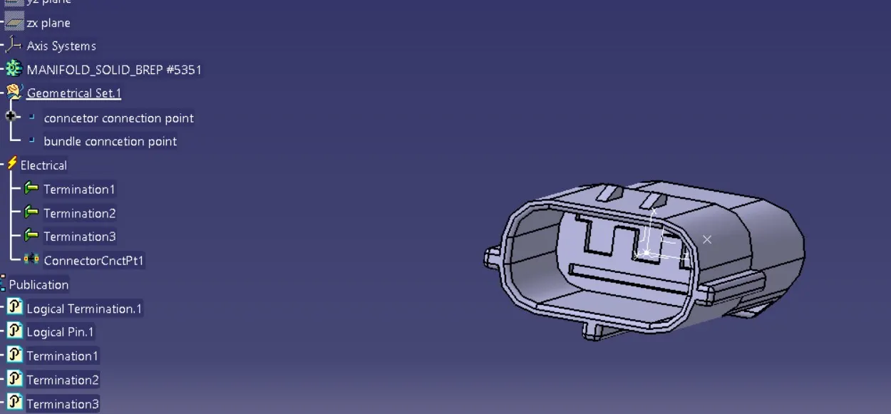
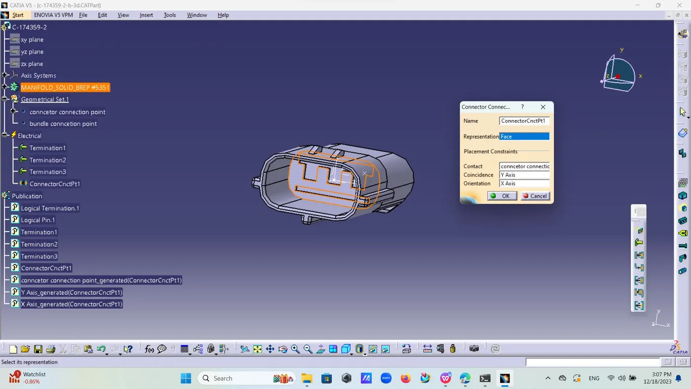
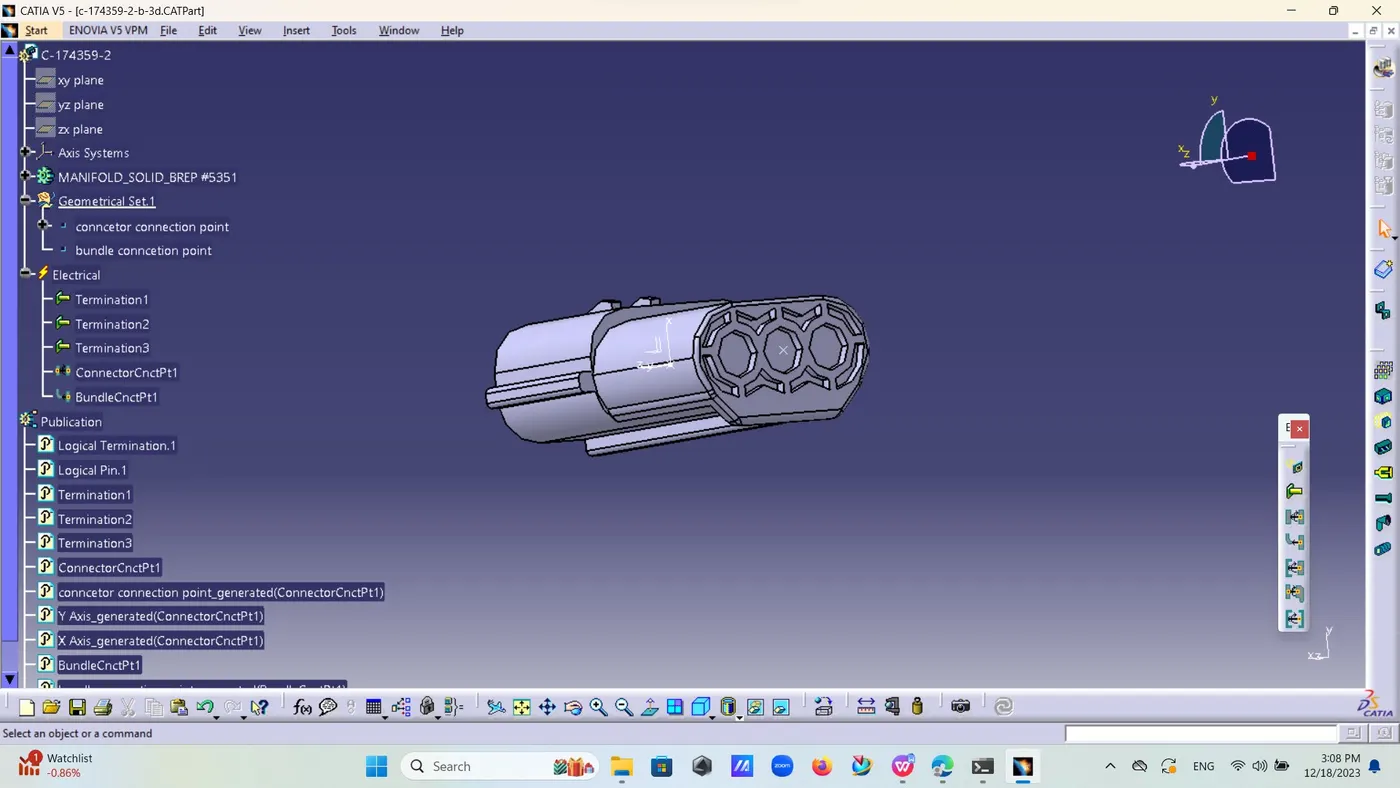
Now define axis system for them by showing y axis exactly opposite of direction shown in its mating part at mating connector and x axis as locking direction and z.
Now,go to electrical part design and define this part electrically by defining its bundle entry connection and connector connection points by selection part as connector .
Now add this all to catalogue .
Now open this three parts in electrical assembly and there is option of electrical connection point definition last connect electrical device and connect them one by one .